Isuzu Trooper (1998-2002 year). Manual - part 567


  Index      Isuzu     Isuzu Trooper - service repair manual 1998-2002 year


Search            


Content   ..  565  566  567  568   ..


Isuzu Trooper (1998-2002 year). Manual - part 567


6A – 76 ENGINE MECHANICAL

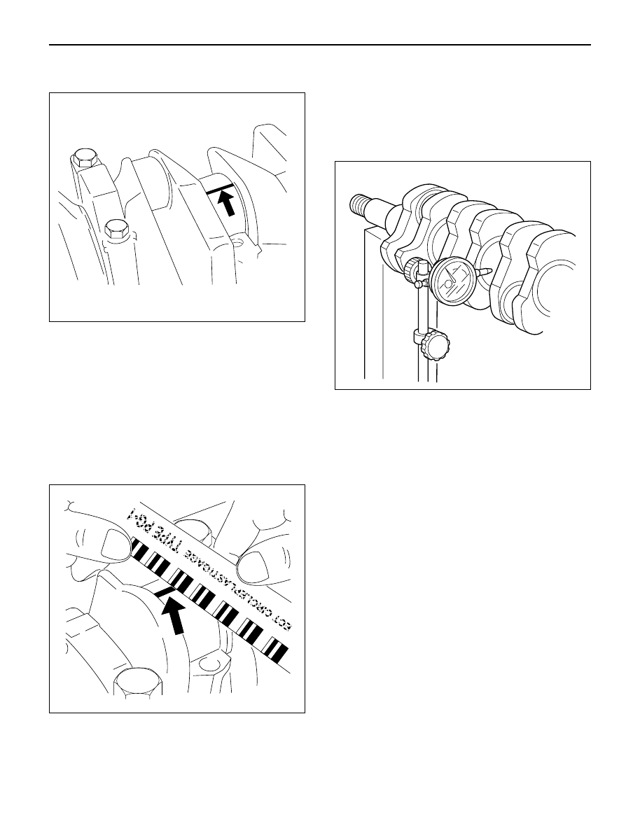
7) Apply plastigage to the crankshaft journal unit as

shown in the illustration.

8) Install the main bearing caps. Apply engine oil to

the bolt threads and the seats. Tighten the bolts
to the specified torque.

Torque: 167 N·m (17 kg·m/123 lb ft)

NOTE: Do not allow the crankshaft to rotate.

9) Remove the main bearing caps.

10) Measure the plastigage width and determine the

oil clearance. If the oil clearance exceeds the
specified limit, replace the main bearings as a
set and/or replace the crankshaft.

11) Clean the plastigage from the bearings and the

crankshaft.
Remove the crankshaft and the bearings.

Standard: 0.031 – 0.063 mm (0.0012 – 0.0025 in)
Limit: 0.11 mm (0.0043 in)

3. Run-out

1) Carefully set the crankshaft on the V-blocks.

Slowly rotate the crankshaft and measure the
runout. If the crankshaft runout exceeds the
specified limit, the crankshaft must be replaced.

Standard: 0.05 mm (0.0020 in) or less
Limit: 0.08 mm (0.0031 in)

Measure the diameter and the uneven wear of
main journal and crank pin.
If the crankshaft wear exceeds the specified
limit, crankshaft must be replaced.

Main journal diameter

Standard: 69.917 – 69.932 mm (2.7526 – 2.7532 in)
Limit: 69.91 mm (2.7524 in)

Crank pin diameter

Standard: 52.915 – 52.930 mm (2.0833 – 2.0839 in)
Limit: 52.90 mm (2.0827 in)

Uneven wear limit

Standard: 0.05 mm (0.0020 in) or less
Limit: 0.08 mm (0.0031 in)

014RW055

014RW077

012RW068

ENGINE MECHANICAL 6A – 77

Crankshaft inspection

Inspect the surface of the crankshaft journals and crank
pins for excessive wear and damage.
Inspect the oil seal fitting surfaces for excessive wear
and damage.
Inspect the oil ports for obstructions.

Crankshaft tufftriding inspection

1. Use an organic cleaner to thoroughly clean the

crankshaft. There must be no traces of on the
surfaces to be inspected.

2. Prepare a 5 – 10% solution of ammonium cupric

chloride (dissolved in distilled water).

3. Use a syringe to apply the solution to the surface to

be inspected.
Hold the surface to be inspected perfectly
horizontal to prevent the solution from running.

NOTE: Do not allow the solution to come in contact with
the oil ports and their surrounding area (Approximately
10 mm).

Judgment

1. Wait for thirty or forty seconds.

If there is no discoloration after thirty or forty
seconds, the crankshaft is usable.
If discoloration appears (the surface being tested
will become the color of copper), the crankshaft
must be replaced.

2. Steam clean the crankshaft surface immediately

after completing the test.

NOTE: The ammonium cupric chloride solution is highly
corrosive. Because of this, it is imperative that the
surfaces being tested be cleaned immediately after
completing the test.

CRANKSHAFT BEARING SECTION

When installing new crankshaft bearings, refer to the
selection table below.
Select and install the new crankshaft bearings, paying
close attention to the cylinder body journal hole
diameter grade mark and the crankshaft journal
diameter grade mark.

NOTE: Although all upper journal bearings (cylinder
body side) have oil grooves and holes, all lower
bearings (bearing cap side) have no groove and hole.
Play close attention to the distinction during the
installation procedure.

012RW045

The portion to be tested
must be held horizontally
so as not to let the test
solution flow.

The sliding surface
of the pin
or journal.

Test liquid should
not be applied to
the area around the
oil port.

Approximately
10mm

F06MV020

012RW038

6A – 78 ENGINE MECHANICAL

Crankshaft Bearing Bore Grade Mark Position

Crankshaft bearing bore grade marks 

1

or 

2

are

stamped on the rear right hand side of the cylinder
body.

Example:

No. 1 Bearing No. 2 Bearing No. 3 Bearing No. 4 Bearing No.  5  Bearing

Housing

Housing

Housing

Housing

Housing

Legend

(1) No. 1 Main bearing bore grade
(2) No. 2 Main bearing bore grade
(3) No. 3 Main bearing bore grade
(4) No. 4 Main bearing bore grade
(5) No. 5 Main bearing bore grade

Crankshaft Journal Grade Mark Position

The crankshaft journal grade marks (1 or –) are
stamped on each crankshaft journal wave.
The crankshaft journal and bearing clearance must be
the same for each position after installation of the
crankshaft and the crankshaft bearings.

Legend

(1) Crankshaft journal outside diameter grade

1

2

1

1

2

1

1

1

1

2

2

2

3

4

5

1

2

3

4

5

012RW114

1

015RW078

012RW069

ENGINE MECHANICAL 6A – 79

Main Bearing

Crankshaft

Bore Diameter  mm(in)

Main Journal Diameter  mm(in)

Crankshaft

Oil Clearance

Grade

Inside Diameter

Grade

Outside Diameter

Bearing

mm(in)

1 or -

69.927 – 69.932

4

0.045 – 0.061

(2.7530 – 2.7532)

(0.0018 – 0.0024)

1

73.992 – 74.000

2 or - - 

69.922 – 69.927

4

0.050 – 0.066

(2.9131 – 2.9134)

(2.7528 – 2.7530)

(0.0020 – 0.0026)

3 or - - -

69.917 – 69.922

5

0.052 – 0.068

(2.7526 – 2.7528)

(0.0020 – 0.0027)

1 or -

69.927 – 69.932

2

0.042 – 0.059

(2.7530 – 2.7532)

(0.0017 – 0.0023)

2

73.983 – 73.992

2 or - - 

69.922 – 69.927

3

0.044 – 0.061

(2.9127 – 2.9131)

(2.7528 – 2.7530)

(0.0017 – 0.0024)

3 or - - -

69.917 – 69.922

4

0.046 – 0.063

(2.7526 – 2.7528)

(0.0018 – 0.0025)

1 or -

69.927 – 69.932

1

0.037 – 0.053

(2.7530 – 2.7532)

(0.0015 – 0.0021)

3

73.975 – 73.983

2 or - - 

69.922 – 69.927

2

0.039 – 0.055

(2.9124 – 2.9127)

(2.7528 – 2.7530)

(0.0015 – 0.0022)

3 or - - -

69.917 – 69.922

2

0.044 – 0.060

(2.7526 – 2.7528)

(0.0017 – 0.0024)

REASSEMBLY

1. Crankshaft

1) Install the main bearings to the cylinder body

and the main bearing caps.

2) Be sure that they are positioned correctly.
3) Apply new engine oil to the upper and lower

main bearing faces.

4) Carefully mount the crankshaft.
5) Apply engine oil to the thrust washer.
6) Assemble the thrust washer to the No. 3 bearing

journal. The oil grooves must face the
crankshaft.

7) Install the bearing caps with the bearing cap

head arrow mark facing the front of the engine.

8) Apply engine oil to the main bearing cap bolts.
9) Tighten the main bearing cap bolts to the

specified torque a little at a time in the sequence
shown in the illustration.

Torque: 167 N·m (17.0 kg·m/123 lb ft)

NOTE: Check to see that the crankshaft turns smoothly
by rotating it manually.

012RW047

8

4

1

5

9

6

10

2

3

7

012RW027


Content   ..  565  566  567  568   ..