Isuzu Trooper (1998-2002 year). Manual - part 533
6E–502
6VE1 3.5 ENGINE DRIVEABILITY AND EMISSIONS
3. Disconnect the fuel hose from the fuel filter on the
engine side.
4. Disconnect the fuel hose from the fuel filter on the fuel
tank side.
5. Remove the bolt on the fuel filter holder.
041RW003
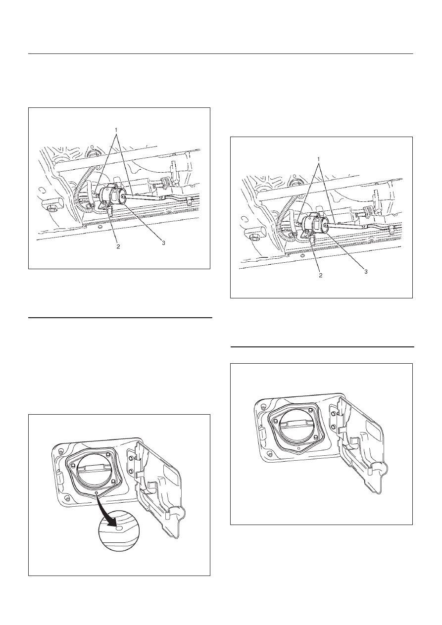
Legend
(1) Fuel Hose
(2) Fuel Filter Fixing Bolt
(3) Fuel Filter
6. Remove the fuel filter.
Inspection Procedure
1. Replace the fuel filter when the following occur:
D
Fuel leaks from the fuel filter body.
D
The fuel filter body is damaged.
D
The fuel filter is clogged with dirt or sediment.
2. If the drain hole is clogged, clean the drain.
060R200242
Installation Procedure
1. Install the fuel filter in the correct direction.
2. Install the bolt on the fuel filter holder.
Tighten
D
Tighten the screws to 20 N·m (14 lb ft.).
3. Connect the fuel hose on the engine side.
4. Connect the fuel hose on the fuel tank side.
041RW003
Legend
(1) Fuel Hose
(2) Fuel Filter Fixing Bolt
(3) Fuel Filter
5. Install the fuel filler cap.
060R200219
6. Connect the negative battery cable.