Isuzu Trooper (1998-2002 year). Manual - part 532
6E–498
6VE1 3.5 ENGINE DRIVEABILITY AND EMISSIONS
Air Cleaner/Air Filter
Removal Procedure
1. Loosen the clamp between the air cleaner lid and the
mass air flow sensor.
060R200240
2. Release the four latches securing the lid to the air
cleaner housing.
3. Remove the air cleaner lid.
4. Remove the air filter element.
5. Remove the retaining bolts and the air cleaner
housing from the vehicle.
060R200220
Legend
(1) Air Cleaner Lid
(2) Air Filter Element
(3) Air Cleaner Housing
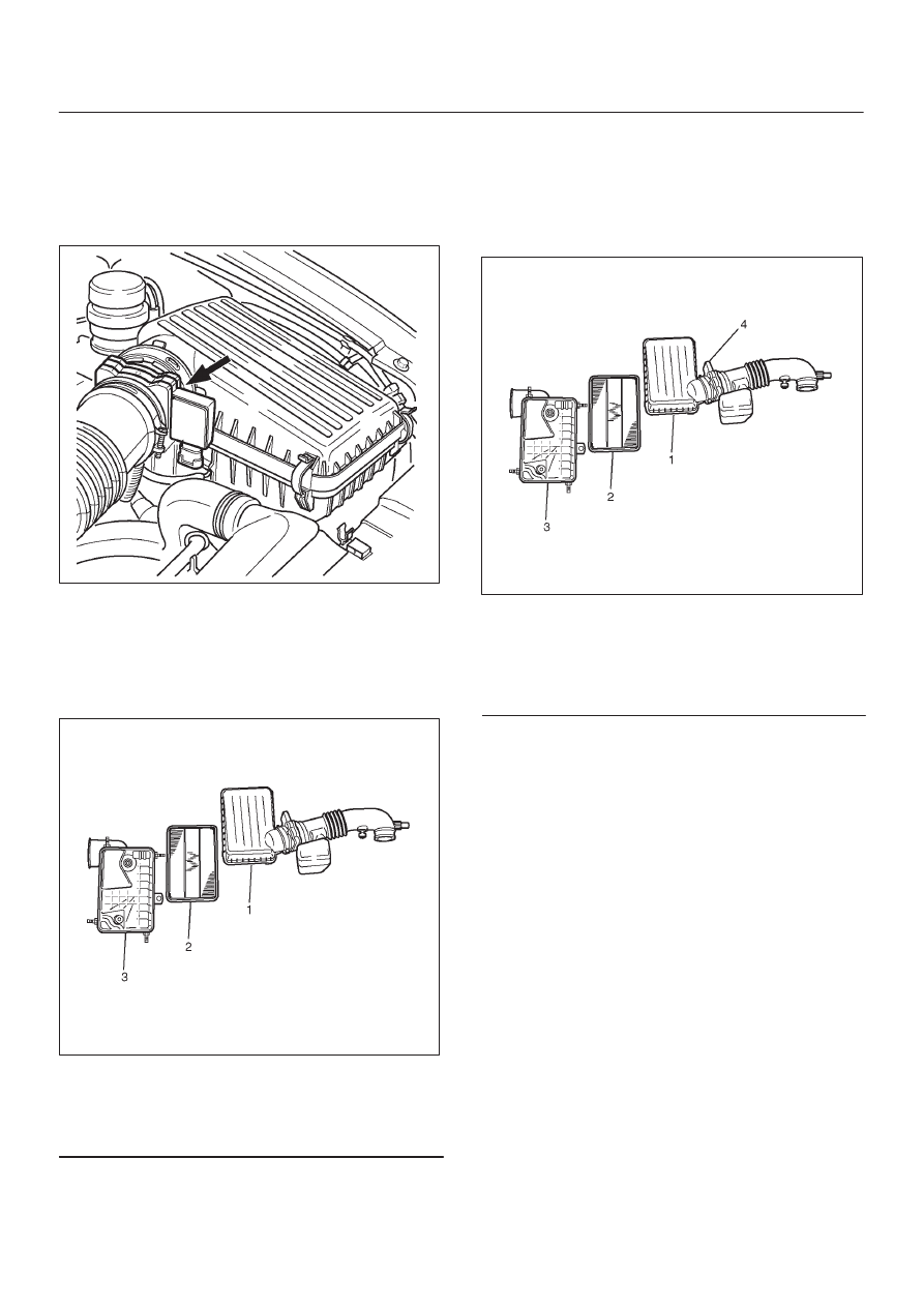
Installation Procedure
1. Install the air cleaner housing in the vehicle with the
retaining bolts.
2. Install the air filter element in the air cleaner housing.
3. Install the air cleaner lid on the MAF sensor and the air
cleaner housing.
060R200241
Legend
(1) Air Cleaner Lid
(2) Air Filter Element
(3) Air Cleaner Housing
(4) Mass Air Flow Sensor
4. Tighten the clamp and secure the four latches
between the lid and the air cleaner housing.
Common Chamber
Removal and Installation Procedure
Refer to Common Chamber in Engine Mechanical
section.