Isuzu Trooper (1998-2002 year). Manual - part 531


  Index      Isuzu     Isuzu Trooper - service repair manual 1998-2002 year


Search            


Content   ..  529  530  531  532   ..


Isuzu Trooper (1998-2002 year). Manual - part 531


6E–494

6VE1 3.5 ENGINE DRIVEABILITY AND EMISSIONS

Malfunction Indicator Lamp

(MIL)

Removal and Installation Procedure

Refer to Warning light bulb, indicator light valve,
illumination light bulb, A/T indicator light bulb in Meter and
Gauge.

Reduced Power Lamp

The reduced power lamp (RPL) turns on when the ignition
key is moved to the ON position. It should turn off in
approximately 3 seconds or immediately after the engine
starts.
If the RPL turns on during vehicle operation, a vehicle
system failure resulting in reduced engine output is
indicated.
If both the reduced RPL and the check engine light turn
on, a serious problem affecting vehicle performance is
indicated.
Refer to the 

OBD system check NO and RPL “ON” steady

in this manual.

Powertrain Control Module

(PCM)

Service Precaution

NOTE: To prevent possible electrostatic discharge
damage to the PCM, do not touch the connector pins or
soldered components on the circuit board.

Electrostatic Discharge (ESD)
Damage

Electronic components used in the control systems are
often designed to carry very low voltage.  Electronic
components are susceptible to damage caused by
electrostatic discharge.  Less than 100 volts of static
electricity can cause damage to some electronic
components.  By comparison, it takes as much as 4,000
volts for a person to even feel the zap of a static
discharge.
There are several ways for a person to become statically
charged.  The most common methods of charging are by
friction and by induction.  An example of charging by
friction is a person sliding across a car seat.
Charging by induction occurs when a person with well
insulated shoes stands near a highly charged object and
momentarily touches ground.  Charges of the same
polarity are drained off leaving the person highly charged
with the opposite polarity.  Static charges can cause
damage, therefore, it is important to use care when
handling and testing electronic components.

NOTE: To prevent possible Electrostatic Discharge
damage, follow these guidelines:

D

Do not touch the control module connector pins or
soldered components on the control module circuit
board.

D

Do not open the replacement part package until the
part is ready to be installed.

D

Before removing the part from the package, ground
the package to a known good ground on the vehicle.

D

If the part has been handled while sliding across the
seat, or while sitting down from a standing position, or
while walking a distance, touch a known good ground
before installing the part.

NOTE: To prevent internal PCM damage, the ignition
must be in the “OFF” position in order to disconnect or
reconnect power to the PCM (for example: battery cable,
PCM pigtail, PCM fuse, jumper cables, etc.).

IMPORTANT:

When replacing the production PCM

with a service PCM, it is important to transfer the
broadcast code and production PCM number to the
service PCM label.  This will allow positive identification of
PCM parts throughout the service life of the vehicle.  Do
not record this information on the metal PCM cover.

IMPORTANT:

The ignition should always be in the

“OFF” position in order to install or remove the PCM
connectors.

Service of the PCM should normally consist of either re-
placement of the PCM or EEPROM programming.  If the
diagnostic procedures call for the PCM to be replaced,
the PCM should be checked first to ensure it is the correct
part.  If it is, remove the faulty PCM and install the new
service PCM.
The service PCM EEPROM will not be programmed.
DTC P0601 indicates the check sum error.

Removal Procedure

1. Disconnect the negative battery cable.
2. Block the wheels.
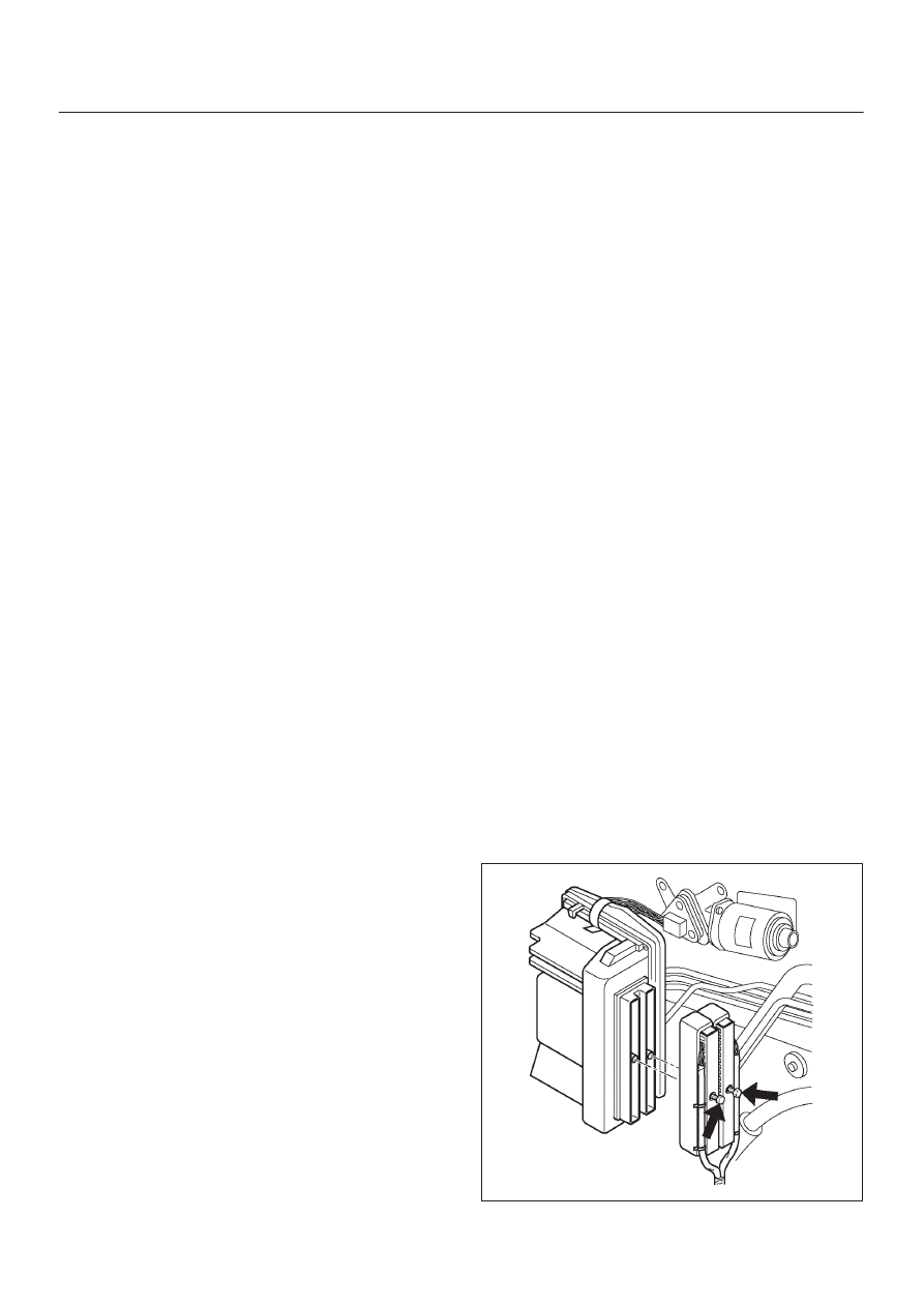
3. Remove the two screws from the PCM electrical

connectors.

4. Disconnect the PCM electrical connectors.

060RY00031

6E–495

6VE1 3.5L ENGINE DRIVEABILITY AND EMISSIONS

5. After removing the clip which fixes the PCM to the

bracket, remove PCM.

060RY00026

Installation Procedure

1. Install the PCM to bracket and fix with the clip.

060RY00025

2. Connect the PCM electrical connectors.
3. Install the two screws to PCM electrical connectors.

060RY00031

6E–496

6VE1 3.5 ENGINE DRIVEABILITY AND EMISSIONS

EEPROM

General Description

The Electronically Erasable Programmable Read Only
Memory (EEPROM) is a permanent memory that is
physically soldered within the PCM.  The EEPROM
contains program and calibration information that the
PCM needs to control powertrain operation.

EEPROM Programming

1. Set-up – Ensure that the following conditions have

been met:

D

The battery is fully charged.

D

The ignition is “ON.”

D

The Vehicle Interface Module cable connection at
the DLC is secure.

2. Program the PCM using the latest software matching

the vehicle.  Refer to up-to-date Techline equipment
user’s instructions.

3. If the PCM fails to program, proceed as follows:

D

Ensure that all PCM connections are OK.

D

Check the Techline equipment for the latest
software version.

D

Attempt to program the PCM.  If the PCM still
cannot be programmed properly, replace the PCM.
The replacement PCM must be programmed.

Functional Check

1. Perform the On-Board Diagnostic System Check.
2. Start the engine and run for one minute.
3. Scan for DTCs using the Tech 2.

Throttle Position (TP) Sensor

Removal Procedure

1. Disconnect the negative battery cable.
2. Disconnect the TPS electrical connector.

3. Remove the bolts and the TP sensor from the throttle

body.

060R200185

NOTE: Do not clean the TP sensor by soaking it in
solvent.  The sensor will be damaged as a result.

Function Check

Use a Tech 2 to check the TP sensor output voltage at
closed throttle.

D

The voltage should be TP1 about 0.4V, TP2 about
4.6V and TP3 about 4.6V.

D

If the reading is abnormal value, check the throttle
shaft to see if it is binding.

Installation Procedure

1. Install the TP sensor on the throttle body with the

bolts.

060R200185

2. Connect the TP electrical connector.
3. Install the negative battery cable.

6E–497

6VE1 3.5L ENGINE DRIVEABILITY AND EMISSIONS

Vehicle Speed Sensor (VSS)

Removal Procedure

CAUTION: The VSS is located on the right side of
the transfer case just ahead of the rear propeller
shaft and very close to the exhaust pipes for 4WD
and on the extension cover for 2WD.  Be sure that the
exhaust pipes are cool enough to touch before trying
to remove the VSS.  If the pipes are hot, you could be
burned.

1. Disconnect the negative battery cable.
2. Disconnect the VSS electrical connector.

TS23748

3. Remove the bolt and the clamp securing the VSS in

place.

IMPORTANT:

Have a container ready to catch any fluid

that leaks out when the VSS is removed from the transfer
case for 4WD and on the extension cover for 2WD.

TS23780

4. Remove the VSS from the transfer case by wiggling it

slightly and pulling it straight out.

Inspection Procedure

1. Inspect the electrical connector for signs of corrosion

or warping.  Replace the VSS if the electrical
connector is corroded or warped.

2. Inspect the VSS driven gear for chips, breaks, or worn

condition.  Replace the VSS if the driven gear is
chipped, broken or worn.

3. Inspect the O-ring for wear, nicks, tears, or

looseness.  Replace the O-ring if necessary.

Installation Procedure

1. Install the VSS in the transfer case with the notch for

the connector facing the rear.

2. Secure the VSS in place with the clamp and the bolt.

Tighten

D

Tighten the bolt to 16 N·m (12 lb ft.).

TS23780

3. Connect the VSS electrical connector.

TS23748

4. Check the transfer case oil level.  Add fluid if

necessary.

5. Connect the negative battery cable.


Content   ..  529  530  531  532   ..