Isuzu Trooper (1998-2002 year). Manual - part 494
6E–346
6VE1 3.5 ENGINE DRIVEABILITY AND EMISSIONS
Diagnostic Trouble Code (DTC)
P1115 ECT Sensor Circuit Intermittent High Voltage
D06R200049
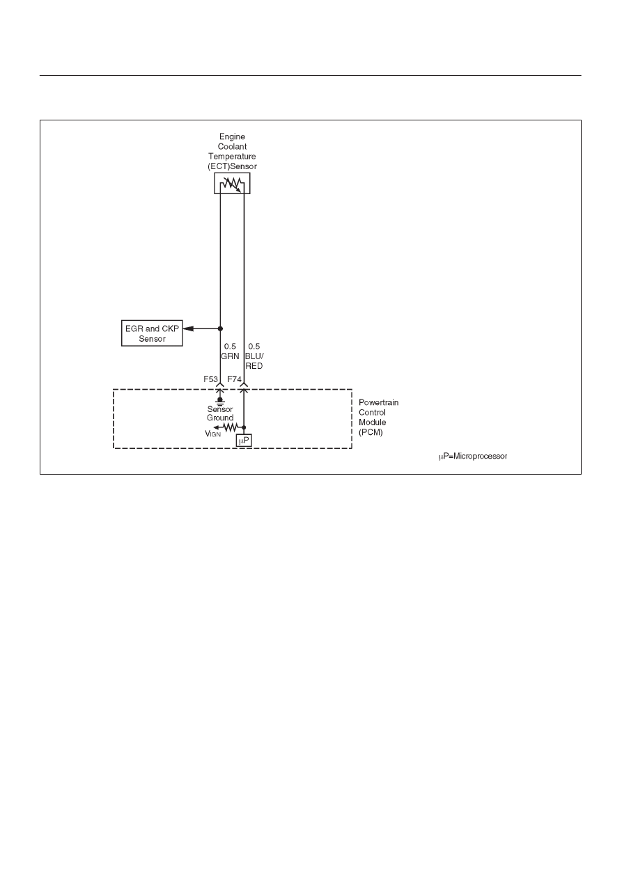
Circuit Description
The engine coolant temperature (ECT) sensor is a
thermistor mounted in the engine coolant stream. The
powertrain control module (PCM) applies a voltage
(about 5.0 volts) through a pull-up resistor to the ECT
signal circuit. When the engine coolant is cold, the sensor
(thermistor) resistance is high, therefore the PCM will
measure a high signal voltage. As the engine coolant
warms, the sensor resistance becomes less, and the
ECT signal voltage measured at the PCM drops. With a
fully warmed up engine, the ECT signal voltage should
measure about 1.5 to 2.0 volts. If the PCM detects an
ECT signal that is intermittently above the range of the
ECT sensor, DTC P1115 will set.
Conditions for Setting the DTC
D
Engine running time longer than 90 seconds.
D
The ECT sensor signal is intermittently greater than
–39
°
C (–38
°
F) (about 5 volts) for a total of 10 seconds
over a 100-second period.
Action Taken When the DTC Sets
D
The PCM will not illuminate the malfunction indicator
lamp (MIL).
D
The PCM will store conditions which were present
when the DTC was set as Failure Records data only.
This information will not be stored as Freeze Frame
data.
Conditions for Clearing the MIL/DTC
D
A history DTC P1115 will clear after 40 consecutive
warm-up cycles have occurred without a fault.
D
DTC P1115 can be cleared by using the Tech 2 “Clear
Info” function or by disconnecting the PCM battery
feed.
Diagnostic Aids
Check for the following conditions:
D
Poor connection at PCM – Inspect harness connectors
for backed-out terminals, improper mating, broken
locks, improperly formed or damaged terminals, and
poor terminal-to-wire connection.
D
Damaged harness – Inspect the wiring harness for
damage. If the harness appears to be OK, observe the
ECT display on the Tech 2 while moving connectors
and wiring harnesses related to the ECT sensor. A
change in the ECT display will indicate the location of
the fault.
Reviewing the Failure Records vehicle mileage since the
diagnostic test last failed may help determine how often