Isuzu Trooper (1998-2002 year). Manual - part 493
6E–342
6VE1 3.5 ENGINE DRIVEABILITY AND EMISSIONS
Diagnostic Trouble Code (DTC)
P1112 IAT Sensor Circuit Intermittent Low Voltage
D06RY00168
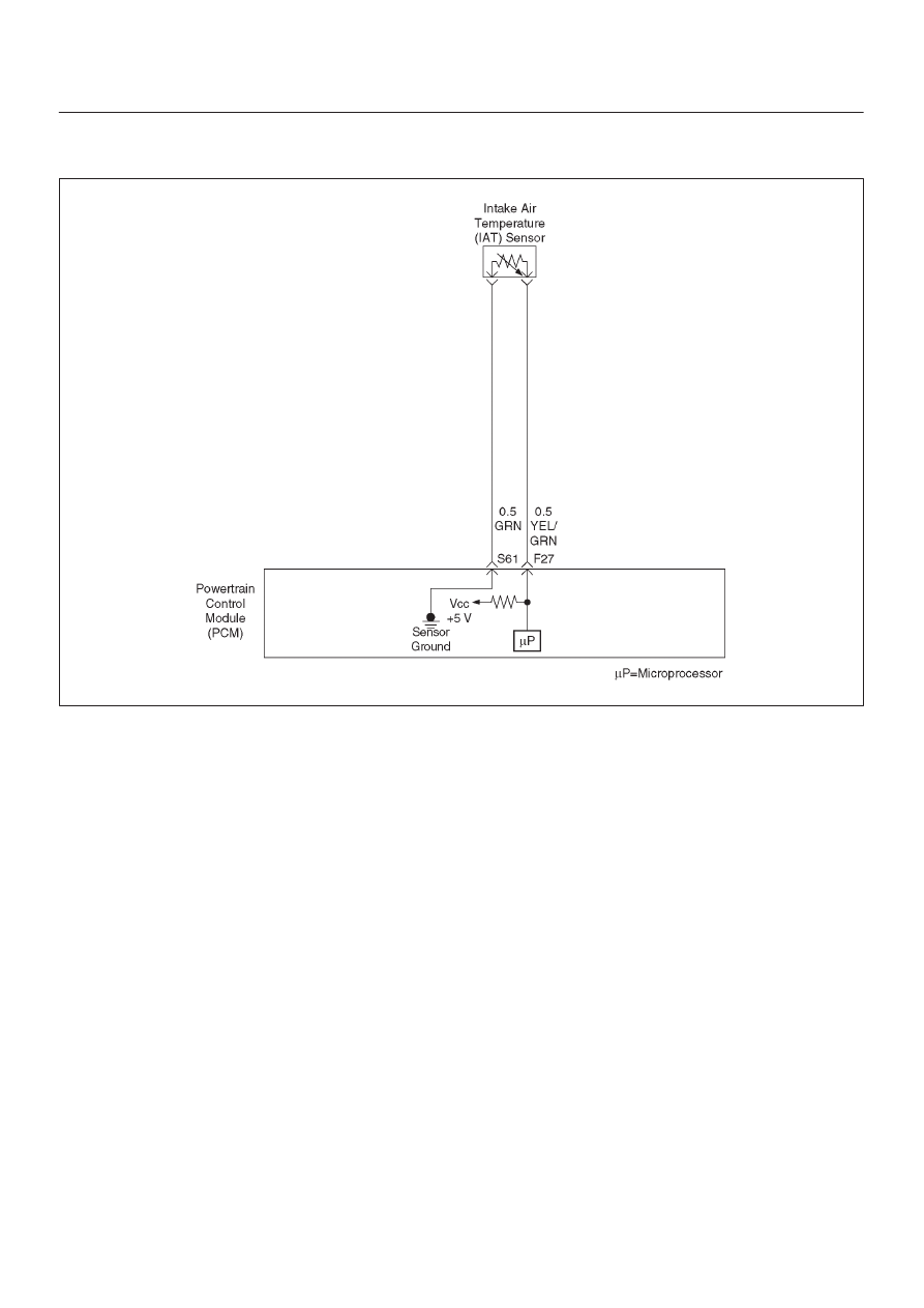
Circuit Description
The intake air temperature (IAT) sensor is a thermistor
which measures the temperature of the air entering the
engine. The powertrain control module (PCM) applies 5
volts through a pull-up resistor to the IAT sensor. When
the intake air is cold, the sensor resistance is high and the
PCM will monitor a high signal voltage on the IAT signal
circuit. If the intake air is warm, the sensor resistance
becomes lower, causing the PCM to monitor a lower
voltage. DTC P1112 will set when the PCM intermittently
detects an excessively low signal voltage on the intake air
temperature sensor signal circuit.
Conditions for Setting the DTC
D
The engine has been running for over 15 seconds.
D
Vehicle speed is greater than 48 km/h (30 mph).
D
IAT signal voltage is greater than 148
°
C (298
°
F)
(about 0.10 volt) for a total of 2.5 seconds over a
25-second period of time.
Action Taken When the DTC Sets
D
The PCM will not illuminate the malfunction indicator
lamp (MIL).
D
The PCM will store conditions which were present
when the DTC was set as Failure Records data only.
This information will not be stored as Freeze Frame
data.
D
The PCM will substitute a default value for intake air
temperature.
Conditions for Clearing the MIL/DTC
D
A history DTC P1112 will clear after 40 consecutive
warm-up cycles have occurred without a fault.
D
DTC P1112 can be cleared by using the Tech 2 “Clear
Info” function or by disconnecting the PCM battery
feed.
Diagnostic Aids
Check for the following conditions:
D
Poor connection at PCM – Inspect harness connectors
for backed-out terminals, improper mating, broken
locks, improperly formed or damaged terminals, and
poor terminal-to-wire connection.
D
Damaged harness – Inspect the wiring harness for
damage. If the harness appears to be OK, observe the
IAT display on the Tech 2 while moving connectors and
wiring harnesses related to the IAT sensor. A change
in the IAT display will indicate the location of the fault.
Reviewing the Failure Records vehicle mileage since the
diagnostic test last failed may help determine how often
the condition that caused the DTC to be set occurs. This
may assist in diagnosing the condition.
Test Description
Number(s) below refer to the step number(s) on the
Diagnostic Chart.