Infiniti I30. Emission Control System (2003 year). Manual - part 45
System Description
NHEC1328
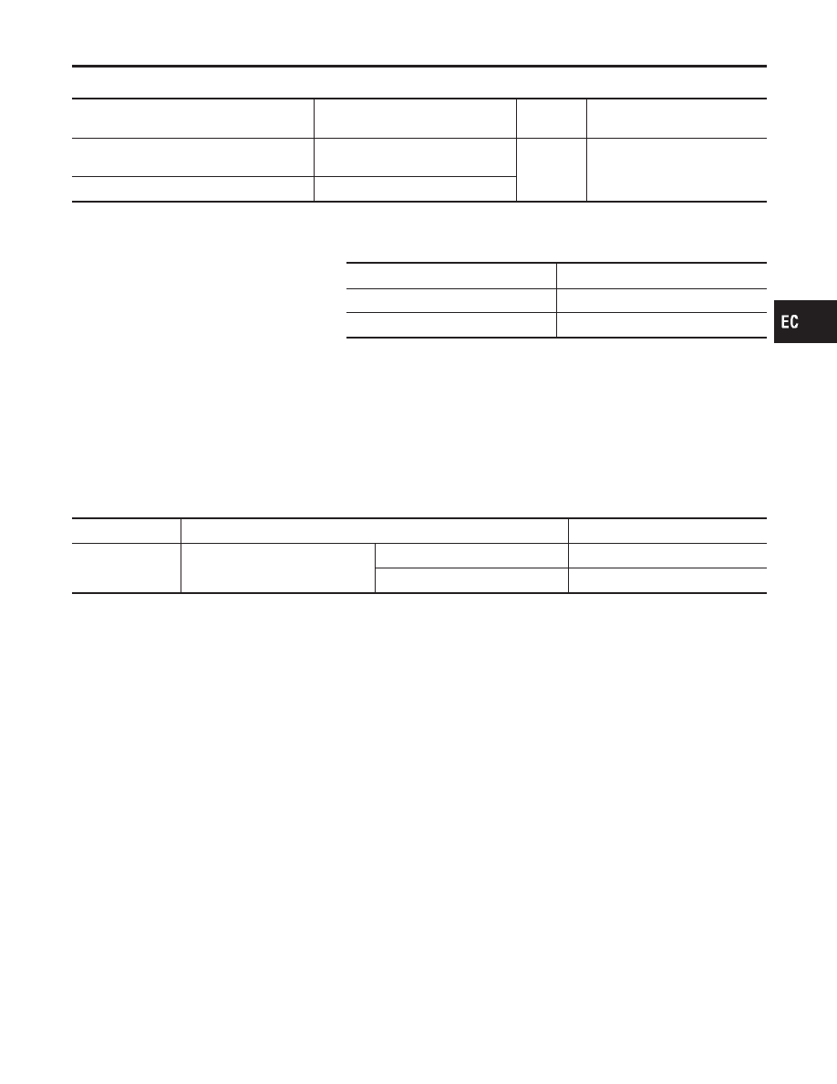
Sensor
Input Signal to ECM
ECM func-
tion
Actuator
Crankshaft position sensor (POS)
Camshaft position sensor (PHASE)
Engine speed
Engine
mount con-
trol
Electronic controlled engine
mount
Wheel sensor
Vehicle speed
The ECM controls the engine mount operation corresponding to
the engine speed and the vehicle speed. The control system has
2-step control [soft/hard].
Vehicle condition
Engine mount control
Idle (with vehicle stopped)
Soft
Driving
Hard
CONSULT-II Reference Value in Data Monitor
Mode
NHEC1329
Specification data are reference values.
MONITOR ITEM
CONDITION
SPECIFICATION
ENGINE MOUNT
쐌
Engine: Running
Idle (With vehicle stopped)
“IDLE”
Except above conditions
“TRVL”
GI
MA
EM
LC
FE
AT
AX
SU
BR
ST
RS
BT
HA
SC
EL
IDX
ELECTRONIC CONTROLLED ENGINE MOUNT
System Description
EC-705