Infiniti QX56 (JA60). Manual - part 471
EM-38
< ON-VEHICLE REPAIR >
ROCKER COVER
ROCKER COVER
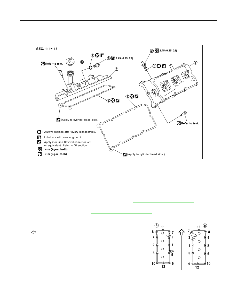
Exploded View
INFOID:0000000005148995
Removal and Installation
INFOID:0000000005148996
REMOVAL
1. Remove the engine room cover using power tool. Refer to
EM-24, "Removal and Installation"
.
2. Move the harness on the upper rocker cover and its peripheral aside.
3. Remove the ignition coils. Refer to
EM-37, "Removal and Installation"
.
4. Remove the PCV hose from the PCV control valves.
5. Loosen the bolts in reverse order shown using power tool for
rocker cover (A) or (B).
•
: Engine front
CAUTION:
Do not hold the rocker cover (RH) (B) by the oil filler neck.
INSTALLATION
1.
Rocker cover (LH)
2.
PCV control valve
3.
O-ring
4.
Rocker cover gasket (LH)
5.
Rocker cover (RH)
6.
PCV control valve
7.
O-ring
8.
Oil filler cap
9.
Rocker cover gasket (RH)
KBIA2508E
WBIA0697E