Infiniti QX56 (JA60). Manual - part 469
EM-30
< ON-VEHICLE REPAIR >
EXHAUST MANIFOLD AND THREE WAY CATALYST
EXHAUST MANIFOLD AND THREE WAY CATALYST
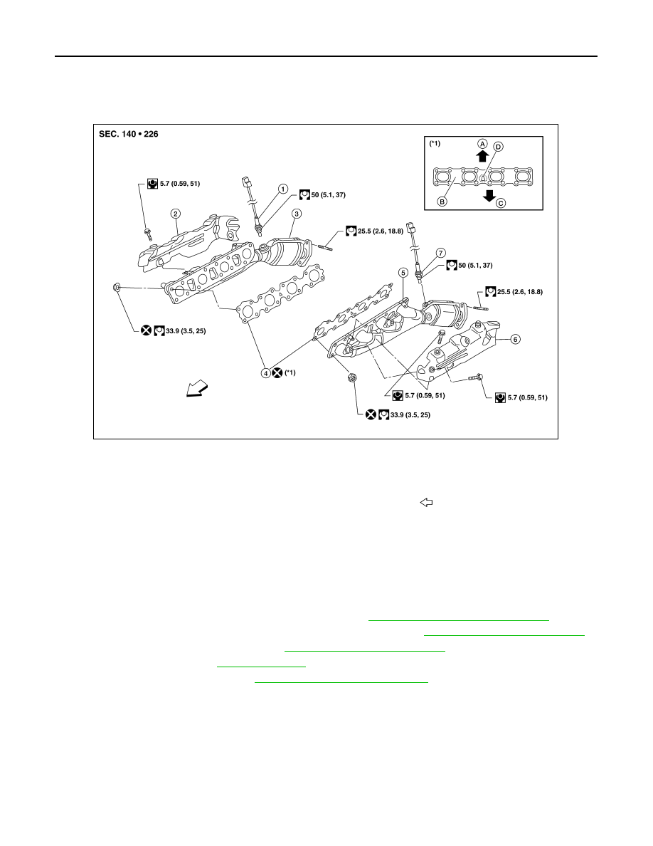
Exploded View
INFOID:0000000005148989
Removal and Installation
INFOID:0000000005148990
REMOVAL
WARNING:
Perform the work when the exhaust and cooling system have cooled sufficiently.
1. Remove the engine undercover (rear) using power tool (4WD models).
2. Remove front final drive assembly (4WD models). Refer to
DLN-215, "Removal and Installation"
.
3. Remove the main muffler assembly and center exhaust tube. Refer to
EX-6, "Removal and Installation"
.
4. Remove the front exhaust tubes. Refer to
EX-6, "Removal and Installation"
5. Remove front tires. Refer to
6. Remove fender protectors. Refer to
EXT-23, "Removal and Installation"
.
7. Remove the LH and RH air fuel ratio A/F sensors.
• Follow steps below to remove each air fuel ratio A/F sensor.
a. Remove the harness connector of each air fuel ratio A/F sensor, and harness from bracket and middle
clamp.
1. Air fuel ratio A/F sensor 1 (bank 2)
2. Exhaust manifold cover (bank 2)
3.
Exhaust manifold (bank 2)
4. Gaskets
5. Exhaust manifold (bank 1)
6.
Exhaust manifold cover (bank 1)
7. Air fuel ratio A/F sensor 1 (bank 1)
A. Up
B. Coated face
C. Manifold side
D. Up mark
Front
AWBIA0453GB