Infiniti QX56 (JA60). Manual - part 1034


  Index      Infiniti     Infiniti QX56 (JA60) - service repair manual 2010 year


Search            


Content   ..  1032  1033  1034  1035   ..


Infiniti QX56 (JA60). Manual - part 1034


WW-12

< FUNCTION DIAGNOSIS >

DIAGNOSIS SYSTEM (BCM)

WIPER : CONSULT-III Function (BCM - WIPER)

INFOID:0000000005369212
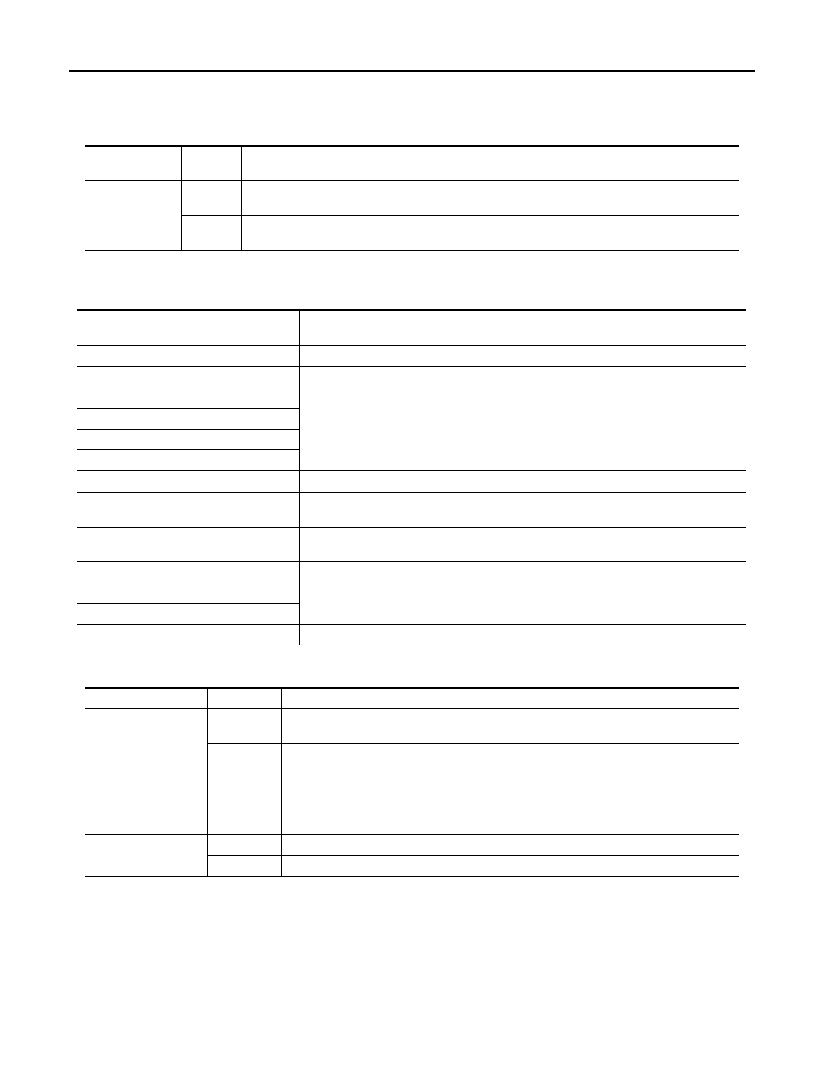
WORK SUPPORT

*: Factory setting

DATA MONITOR

ACTIVE TEST

Work Item

Setting 

Item

Description

WIPER SPEED 
SETTING

ON*

With vehicle speed
(Front wiper intermittent time linked with the vehicle speed and wiper intermittent dial position)

OFF

Without vehicle speed
(Front wiper intermittent time linked with the wiper intermittent dial position)

Monitor Item

[Unit]

Description

IGN ON SW [ON/OFF]

Ignition switch ON status judged from ignition power supply

IGN SW CAN [ON/OFF]

Ignition switch ON status received from IPDM E/R via CAN communication

FR WIPER HI [ON/OFF]

Each switch status that BCM judges from the combination switch reading function

FR WIPER LOW [ON/OFF]

FR WIPER INT [ON/OFF]

FR WASHER SW [ON/OFF]

INT VOLUME [1 - 7]

Each switch status that BCM judges from the combination switch reading function

FR WIPER STOP [ON/OFF]

Front wiper motor (stop position) status received from IPDM E/R with CAN communica-
tion

VEHICLE SPEED [km/h]

The value of the vehicle speed signal received from combination meter with CAN com-
munication

RR WIPER ON [ON/OFF]

Each switch status that BCM judges from the combination switch reading function

RR WIPER INT [ON/OFF]

RR WASHER SW [ON/OFF]

RR WIPER STOP [ON/OFF]

Rear wiper motor (stop position) status input from the rear wiper motor

Test Item

Operation

Description

FR WIPER

HI

Transmits the front wiper request signal (HI) to IPDM E/R with CAN communication to op-
erate the front wiper HI operation.

LO

Transmits the front wiper request signal (LO) to IPDM E/R with CAN communication to 
operate the front wiper LO operation.

INT

Transmits the front wiper request signal (INT) to IPDM E/R with CAN communication to 
operate the front wiper INT operation.

OFF

Stops transmitting the front wiper request signal to stop the front wiper operation.

RISE UP WIPER 
TEST

ON

Outputs the voltage to operate the rear wiper motor.

OFF

Stops the voltage to stop.

DIAGNOSIS SYSTEM (IPDM E/R)

WW-13

< FUNCTION DIAGNOSIS >

C

D

E

F

G

H

I

J

K

M

A

B

WW

N

O

P

DIAGNOSIS SYSTEM (IPDM E/R)

Diagnosis Description

INFOID:0000000005369213

AUTO ACTIVE TEST

Description

In auto active test mode, the IPDM E/R sends a drive signal to the following systems to check their operation.

• Oil pressure low/coolant pressure high warning indicator

• Oil pressure gauge

• Rear window defogger

• Front wipers

• Tail, license and parking lamps

• Front fog lamps

• Headlamps (Hi, Lo)

• A/C compressor (magnetic clutch)

• Cooling fan

Operation Procedure

1. Close the hood and front door RH, and lift the wiper arms from the windshield (to prevent windshield dam-

age due to wiper operation).

NOTE:

When auto active test is performed with hood opened, sprinkle water on windshield before hand.

2. Turn ignition switch OFF.
3. Turn the ignition switch ON and, within 20 seconds, press the front door switch LH 10 times. Then turn the

ignition switch OFF.

4. Turn the ignition switch ON within 10 seconds. After that the horn sounds once and the auto active test

starts.

5. After a series of the following operations is repeated 3 times, auto active test is completed.
NOTE:

When auto active test mode has to be cancelled halfway through test, turn ignition switch OFF.

CAUTION:

• If auto active test mode cannot be actuated, check door switch system. Refer to 

DLK-71, "Descrip-

tion"

.

• Do not start the engine.

Inspection in Auto Active Test Mode

When auto active test mode is actuated, the following 7 steps are repeated 3 times.

Operation 
sequence

Inspection Location

Operation

1

Rear window defogger

10 seconds 

2

Front wipers

LO for 5 seconds 

→ HI for 5 seconds

WKIA4655E

WW-14

< FUNCTION DIAGNOSIS >

DIAGNOSIS SYSTEM (IPDM E/R)

Concept of auto active test

• IPDM E/R starts the auto active test with the door switch signals transmitted by BCM via CAN communica-

tion. Therefore, the CAN communication line between IPDM E/R and BCM is considered normal if the auto

active test starts successfully.

• The auto active test facilitates troubleshooting if any systems controlled by IPDM E/R cannot be operated.

Diagnosis chart in auto active test mode

3

Tail, license and parking lamps

10 seconds

4

Front fog lamps

10 seconds

5

Headlamps

LO for 10 seconds 

→ HI on-off for 5 seconds

6

A/C compressor (magnet clutch)

ON 

⇔ OFF 5 times

7

Cooling fan

10 seconds

Operation 
sequence

Inspection Location

Operation

WKIA5163E

Symptom

Inspection contents

Possible cause

Oil pressure low warning indicator does not operate

Perform auto active test.
Does the oil pressure low 
warning indicator operate?

YES

• IPDM E/R signal input cir-

cuit

• ECM signal input circuit
• CAN communication signal 

between ECM and combi-
nation meter

NO

• CAN communication signal 

between IPDM E/R, BCM 
and combination meter

Oil pressure gauge does not operate

Perform auto active test.
Does the oil pressure gauge 
operate?

YES

IPDM E/R signal input circuit

NO

• CAN communication signal 

between IPDM E/R, BCM 
and combination meter

Rear window defogger does not operate

Perform auto active test.
Does the rear window defog-
ger operate?

YES

BCM signal input circuit

NO

• Harness or connector be-

tween A/C and AV switch 
assembly and AV control 
unit

• CAN communication signal 

between BCM and IPDM E/
R

DIAGNOSIS SYSTEM (IPDM E/R)

WW-15

< FUNCTION DIAGNOSIS >

C

D

E

F

G

H

I

J

K

M

A

B

WW

N

O

P

CONSULT - III Function (IPDM E/R)

INFOID:0000000005369214

APPLICATION ITEM

CONSULT-III performs the following functions via CAN communication with IPDM E/R.

SELF DIAGNOSTIC

Refer to 

PCS-32, "DTC Index"

.

DATA MONITOR

Monitor item

Any of the following components do not operate

• Front wipers
• Tail  lamps
• License plate lamps
• Parking  lamps
• Front fog lamps
• Headlamps (Hi, Lo)

Perform auto active test.
Does the applicable system 
operate?

YES

BCM signal input system

NO

• Lamp or front wiper motor 

malfunction

• Lamp or front wiper motor 

ground circuit

• Harness or connector be-

tween IPDM E/R and appli-
cable system

• IPDM E/R (integrated relay 

malfunction)

A/C compressor does not operate

Perform auto active test.
Does the A/C compressor op-
erate?

YES

• BCM signal input circuit
• CAN communication signal 

between BCM and ECM

• CAN communication signal 

between ECM and IPDM E/
R

NO

• Magnetic clutch malfunction
• Harness or connector be-

tween IPDM E/R and mag-
netic clutch

• IPDM E/R (integrated relay 

malfunction)

Cooling fan does not operate

Perform auto active test.
Does the cooling fan operate?

YES

• ECM signal input circuit
• CAN communication signal 

between ECM and IPDM E/
R

NO

• Cooling fan motor malfunc-

tion

• Harness or connector be-

tween IPDM E/R and cool-
ing fan

• IPDM E/R (integrated relay 

malfunction)

Symptom

Inspection contents

Possible cause

Diagnosis mode

Description

Self Diagnostic Result

Displays the diagnosis results judged by IPDM E/R.

Data Monitor

Displays the real-time input/output data from IPDM E/R input/output data.

Active Test

IPDM E/R can provide a drive signal to electronic components to check their operations.

CAN Diag Support Monitor

The results of transmit/receive diagnosis of CAN communication can be read.

Monitor Item

[Unit]

MAIN SIG-

NALS

Description

MOTOR FAN REQ
[1/2/3/4]

×

Displays the status of the cooling fan speed request signal received from ECM via 
CAN communication.

A/C COMP REQ
[OFF/ON]

×

Displays the status of the A/C request signal received from AV control unit via 
CAN communication.


Content   ..  1032  1033  1034  1035   ..