Content .. 1030 1031 1032 1033 ..
Infiniti QX56 (JA60). Manual - part 1032
WW-4
< FUNCTION DIAGNOSIS >
FRONT WIPER AND WASHER SYSTEM
FUNCTION DIAGNOSIS
FRONT WIPER AND WASHER SYSTEM
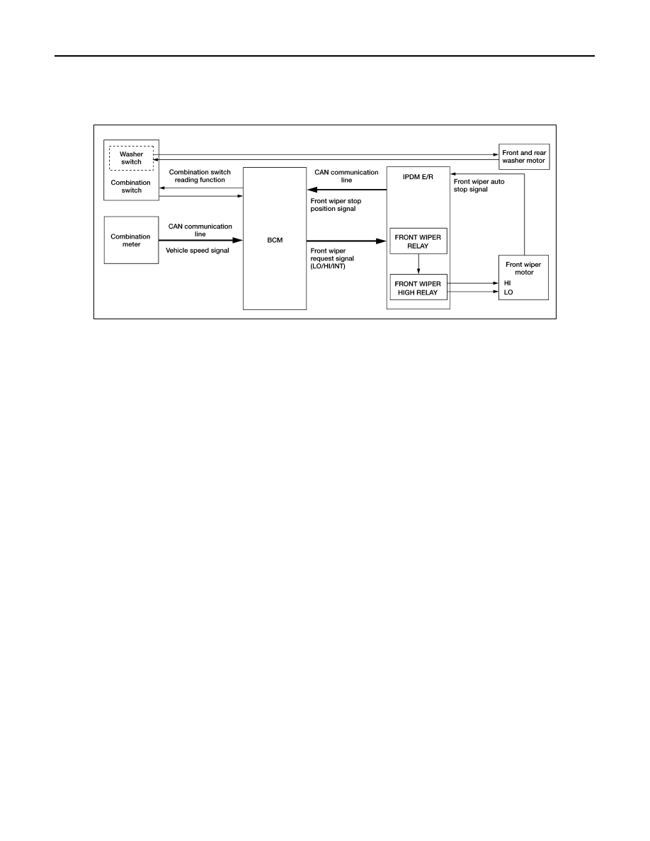
System Diagram
INFOID:0000000005146758
System Description
INFOID:0000000005146759
OUTLINE
The front wiper is controlled by each function of BCM and IPDM E/R.
Control by BCM
• Combination switch reading function
• Front wiper control function
Control by IPDM E/R
• Front wiper control function
• Relay control function
FRONT WIPER BASIC OPERATION
• BCM detects the combination switch condition by the combination switch reading function.
• BCM transmits the front wiper request signal to IPDM E/R with CAN communication depending on each
operating condition of the front wiper.
• IPDM E/R turns ON/OFF the integrated front wiper relay and the front wiper high relay according to the front
wiper request signal. IPDM E/R provides the power supply to operate the front wiper HI/LO operation.
FRONT WIPER LO OPERATION
• BCM transmits the front wiper request signal (LO) to IPDM E/R with CAN communication according to the
front wiper LO operating condition.
Front wiper LO operating condition
- Ignition switch ON
- Front wiper switch LO or front wiper switch MIST (while pressing)
• IPDM E/R turns ON the integrated front wiper relay according to the front wiper request signal (LO).
FRONT WIPER HI OPERATION
• BCM transmits the front wiper request signal (HI) to IPDM E/R with CAN communication according to the
front wiper HI operating condition.
Front wiper HI operating condition
- Ignition switch ON
- Front wiper switch HI
• IPDM E/R turns ON the integrated front wiper relay and the front wiper high relay according to the front wiper
request signal (HI).
FRONT WIPER INT OPERATION (LINKED WITH VEHICLE SPEED)
ALLIA0427GB