Infiniti QX56 (Z62). Manual - part 820


  Index      Infiniti     Infiniti QX56 (Z62) - service repair manual 2011 year


Search            


Content   ..  818  819  820  821   ..


Infiniti QX56 (Z62). Manual - part 820


INL-10

< SYSTEM DESCRIPTION >

SYSTEM

Each function of interior room lamp battery saver can be set by CONSULT-III. Refer to 

INL-15, "BATTERY

SAVER : CONSULT-III Function (BCM - BATTERY SAVER)"

.

ILLUMINATION CONTROL SYSTEM

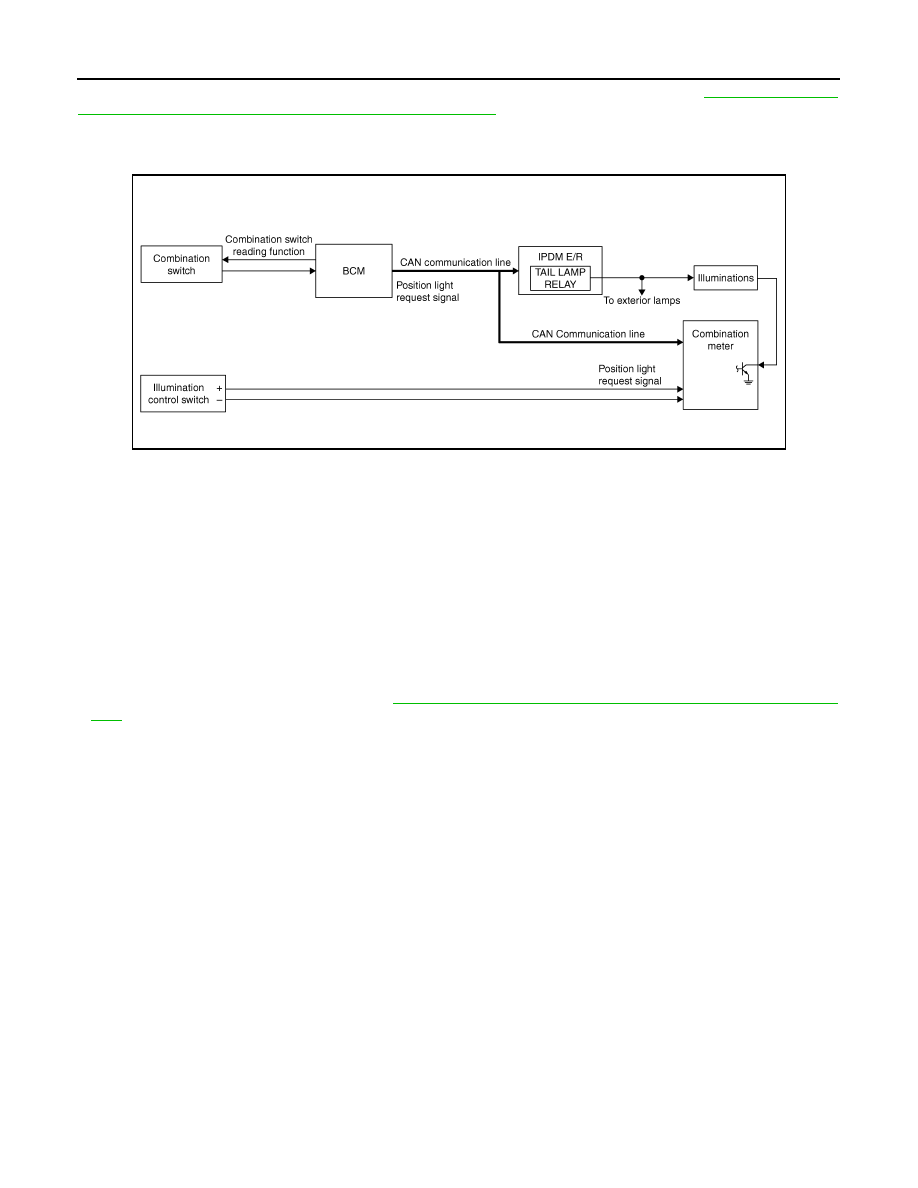
ILLUMINATION CONTROL SYSTEM : System Diagram

INFOID:0000000006216054

ILLUMINATION CONTROL SYSTEM : System Description

INFOID:0000000006216055

OUTLINE

Each illumination lamp is controlled by each function of BCM, IPDM E/R and combination meter.

Control by BCM

• Combination switch reading function
• Headlamp control function

Control by IPDM E/R

• Relay control function

Control by combination meter

• Meter illumination control function (Refer to 

MWI-16, "METER ILLUMINATION CONTROL : System Descrip-

tion"

.)

ILLUMINATION CONTROL

• BCM detects the combination switch condition by the combination switch reading function.
• BCM transmits position light request signal to IPDM E/R and combination meter according to tail lamp ON

condition.

Tail lamp ON condition

- Lighting switch 1ST
- Lighting switch 2ND
- Lighting switch AUTO, and the auto light function ON judgment
- Lighting switch AUTO, with the front fog lamp switch ON and the ignition switch ON
• IPDM E/R turns the integrated tail lamp relay ON according to position light request signal. It provides the

power supply to each illumination lamp. 

• Combination meter enters in the nighttime mode according to position light request signal. Under the night-

time mode the combination meter controls the illuminance by controlling each illumination lamp (ground
side).

AUTO LIGHT ADJUSTMENT SYSTEM

JPLIA0855GB

SYSTEM

INL-11

< SYSTEM DESCRIPTION >

C

D

E

F

G

H

I

J

K

M

A

B

INL

N

O

P

AUTO LIGHT ADJUSTMENT SYSTEM : System Diagram

INFOID:0000000006216056

AUTO LIGHT ADJUSTMENT SYSTEM : System Description

INFOID:0000000006216057

OUTLINE

 Auto light adjustment system is controlled by each function of BCM, combination meter and AV control unit

Control by BCM

• Auto light system
• Auto light adjustment system

AUTO LIGHT ADJUSTMENT SYSTEM

Description

• BCM supplies voltage to the optical sensor when the ignition switch is turned ON or ACC.
• Optical sensor converts outside brightness (lux) to voltage and transmits the optical sensor signal to BCM.
• BCM judges dimming/brightening of combination meter and display according to brightness outside the vehi-

cle, when ignition switch is ON.

• BCM transmits dimmer signal to combination meter via CAN communication, according to auto light adjust-

ment conditions. Dimmer signal is also transmitted to AV control unit.

NOTE:
As to dimming/brightening timing, the sensitivity depends on settings. The settings can be changed with CON-
SULT-III. Refer to 

EXL-23, "HEADLAMP : CONSULT-III Function (BCM - HEAD LAMP)"

.

Auto Light Adjustment Timing Table

When the ignition switch is ON, the illumination of combination meter and display switches dimming/brighten-
ing in the following condition.

BCM switches the illumination of combination meter and display to dimming when outside brightening
obtained from the optical sensor signal is 1250 lx or less for 3 seconds or more. And BCM switches the illumi-
nation of combination meter and display to brightening when outside brightening from the optical sensor signal
is 2500 lx or more for 5 seconds or more.

JMLIA0967GB

Combination meter and display

Dimming/brightening timing

Dimming

Outside brightness is 1250 lx or less for 3 seconds or more.

Brightening

Outside brightness is 2500 lx or more for 5 seconds or more.

INL-12

< SYSTEM DESCRIPTION >

DIAGNOSIS SYSTEM (BCM)

DIAGNOSIS SYSTEM (BCM)

COMMON ITEM

COMMON ITEM : CONSULT-III Function (BCM - COMMON ITEM)

INFOID:0000000006368143

APPLICATION ITEM

CONSULT-III performs the following functions via CAN communication with BCM.

SYSTEM APPLICATION

BCM can perform the following functions for each system.
NOTE:
It can perform the diagnosis modes except the following for all sub system selection items.

×

: Applicable item

*: This item is indicated, but not used.

FREEZE FRAME DATA (FFD)

The BCM records the following vehicle condition at the time a particular DTC is detected, and displays on
CONSULT-III.

Diagnosis mode

Function Description

Work Support

Changes the setting for each system function.

Self Diagnostic Result

Displays the diagnosis results judged by BCM. Refer to 

BCS-57, "DTC Index"

.

CAN Diag Support Monitor

Monitors the reception status of CAN communication viewed from BCM. Refer to CONSULT-III opera-
tion manual.

Data Monitor

The BCM input/output signals are displayed.

Active Test

The signals used to activate each device are forcibly supplied from BCM.

Ecu Identification

The BCM part number is displayed.

Configuration

• Read and save the vehicle specification.
• Write the vehicle specification when replacing BCM.

System

Sub system selection item

Diagnosis mode

Work Support

Data Monitor

Active Test

Door lock

DOOR LOCK

×

×

×

Rear window defogger

REAR DEFOGGER

×

×

Warning chime

BUZZER

×

×

Interior room lamp timer

INT LAMP

×

×

×

Exterior lamp

HEAD LAMP

×

×

×

Wiper and washer

WIPER

×

×

×

Turn signal and hazard warning lamps

FLASHER

×

×

×

AIR CONDITONER*

×

×

• Intelligent Key system
• Engine start system

INTELLIGENT KEY

×

×

×

Combination switch

COMB SW

×

Body control system

BCM

×

IVIS

IMMU

×

×

×

Interior room lamp battery saver

BATTERY SAVER

×

×

×

Back door

TRUNK

×

Vehicle security system

THEFT ALM

×

×

×

RAP system

RETAINED PWR

×

Signal buffer system

SIGNAL BUFFER

×

×

DIAGNOSIS SYSTEM (BCM)

INL-13

< SYSTEM DESCRIPTION >

C

D

E

F

G

H

I

J

K

M

A

B

INL

N

O

P

INT LAMP

CONSULT screen item

Indication/Unit

Description

Vehicle Speed

km/h

Vehicle speed of the moment a particular DTC is detected

Odo/Trip Meter

km

Total mileage (Odometer value) of the moment a particular DTC is detected

Vehicle Condition

SLEEP>LOCK

Power position status of 
the moment a particular 
DTC is detected

While turning BCM status from low power consumption mode to 
normal mode (Power supply position is “LOCK”)

SLEEP>OFF

While turning BCM status from low power consumption mode to 
normal mode (Power supply position is “OFF”.)

LOCK>ACC

While turning power supply position from “LOCK” to “ACC”

ACC>ON

While turning power supply position from “ACC” to “IGN”

RUN>ACC

While turning power supply position from “RUN” to “ACC” (Vehicle 
is stopping and selector lever is except P position.)

CRANK>RUN

While turning power supply position from “CRANKING” to “RUN” 
(From cranking up the engine to run it)

RUN>URGENT

While turning power supply position from “RUN“ to “ACC” (Emer-
gency stop operation)

ACC>OFF

While turning power supply position from “ACC” to “OFF”

OFF>LOCK

While turning power supply position from “OFF” to “LOCK”

OFF>ACC

While turning power supply position from “OFF” to “ACC”

ON>CRANK

While turning power supply position from “IGN” to “CRANKING”

OFF>SLEEP

While turning BCM status from normal mode (Power supply posi-
tion is “OFF”.) to low power consumption mode

LOCK>SLEEP

While turning BCM status from normal mode (Power supply posi-
tion is “LOCK”.) to low power consumption mode

LOCK

Power supply position is “LOCK” (Ignition switch OFF with steer-
ing is locked.)

OFF

Power supply position is “OFF” (Ignition switch OFF with steering 
is unlocked.)

ACC

Power supply position is “ACC” (Ignition switch ACC)

ON

Power supply position is “IGN” (Ignition switch ON with engine 
stopped)

ENGINE RUN

Power supply position is “RUN” (Ignition switch ON with engine 
running)

CRANKING

Power supply position is “CRANKING” (At engine cranking)

IGN Counter

0 - 39

The number of times that ignition switch is turned ON after DTC is detected
• The number is 0 when a malfunction is detected now.
• The number increases like 1 

 2 

 3...38 

 39 after returning to the normal condition 

whenever ignition switch OFF 

 ON.

• The number is fixed to 39 until the self-diagnosis results are erased if it is over 39.


Content   ..  818  819  820  821   ..