Infiniti QX56 (Z62). Manual - part 659


  Index      Infiniti     Infiniti QX56 (Z62) - service repair manual 2011 year


Search            


Content   ..  657  658  659  660   ..


Infiniti QX56 (Z62). Manual - part 659


EM-76

< REMOVAL AND INSTALLATION >

CAMSHAFT

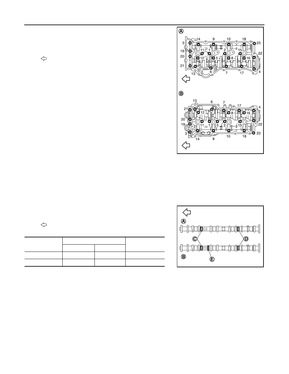
• Loosen mounting bolts (gold color) in the reverse order as

shown in the figure.

CAUTION:

• Never loosen adjusting bolts and mounting bolts (black

color).

• When removing VVEL ladder assembly, hold the drive

shaft from below so as not to drop it.

6.

Remove exhaust camshaft.

7.

Remove valve lifter, if necessary.
• Identify installation positions, and store them without mixing them up.

INSTALLATION

1.

Install valve lifter.
• Install it in the original position.

2.

Install exhaust camshaft.
• Distinction between exhaust camshaft is performed with the

identification mark.

3.

Install VVEL ladder assembly as per the following:

A

:  Bank  2

B

:  Bank  1

: Engine front

JPBIA3513ZZ

: Engine front

Bank

Paint marks

Identification rib (E)

M1 (C)

M2 (D)

Bank 1 (A)

No

Purple

Yes

Bank 2 (B)

No

Purple

No

JPBIA3514ZZ

CAMSHAFT

EM-77

< REMOVAL AND INSTALLATION >

C

D

E

F

G

H

I

J

K

L

M

A

EM

N

P

O

a.

Apply a continuous bead of liquid gasket with tube presser
(commercial service tool) to the VVEL ladder assembly as
shown in the figure.

Use Genuine RTV silicone sealant or equivalent. Refer to

GI-22, "Recommended Chemical Products and Sealants"

.

b.

Tighten mounting bolts in the following step, in numerical order
as shown.

i.

Tighten bolts in numerical order as shown.

ii.

Tighten bolts in numerical order as shown.

iii.

Tighten bolts in numerical order as shown.

4.

Install camshaft sprockets and timing chains. Refer to 

EM-61, "Exploded View"

.

5.

Install VVEL actuator housing assembly. Refer to 

EM-36, "Removal and Installation"

.

6.

Inspect the valve clearance. Refer to 

EM-12, "Inspection"

.

7.

Install in the reverse order of removal.

8.

When New VVEL ladar assembly used. Adjust VVEL control shaft position sensor. Refer to 

EC-150,

"Work Procedure"

.

Inspection

INFOID:0000000006289570

EXHAUST CAMSHAFT VALVE CLEARANCE ADJUSTMENT

• Perform adjustment depending on selected head thickness of valve lifter (EXH).

A

:  Bank  1

B

:  Bank  2

c

φ

3.4 - 4.4 mm (0.134 - 0.173 in) 

: Engine front

JPBIA3515ZZ

A

:  Bank  2

B

:  Bank  1

: Engine front

: 1.96 N·m (0.20 kg-m, 1 ft-lb)

: 5.88 N·m (0.60 kg-m, 4 ft-lb)

: 10.4 N·m (1.1 kg-m, 8 ft-lb)

JPBIA3513ZZ

EM-78

< REMOVAL AND INSTALLATION >

CAMSHAFT

1.

Measure the valve clearance. Refer to 

EM-12, "Inspection"

.

2.

Remove VVEL ladder assembly and exhaust camshaft. Refer to 

EM-75, "Removal and Installation"

.

CAUTION:

Never loosen adjusting bolts and mounting bolts (black color) of VVEL ladder assembly.

3.

Remove valve lifter (EXH) at the locations that are out of the standard.

4.

Measure the center thickness of the removed valve lifters (EXH)
with a micrometer (A).

5.

Use the equation below to calculate valve lifter (EXH) thickness for replacement.

• Thickness of new valve lifter (EXH) can be identified by stamp

marks on the reverse side (inside the cylinder).
Stamp mark 788 indicates 7.88 mm (0.3102 in) in thickness.

Available thickness of valve lifter (EXH): 27 sizes with range 7.88 to 8.40 mm (0.3102 to 0.3307 in) in
steps of 0.02 mm (0.0008 in) (when manufactured at factory). Refer to 

EM-133, "Camshaft"

.

6.

Install selected valve lifter (EXH).

7.

Install VVEL ladder assembly and exhaust camshaft. Refer to 

EM-75, "Removal and Installation"

.

8.

Manually turn crankshaft pulley a few turns. 

9.

Check that the valve clearances for cold engine are within the specifications by referring to the specified
values. Refer to 

EM-12, "Inspection"

.

10. Install all removed parts in the reverse order of removal. 
11. Warm up the engine, and check for unusual noise and vibration.

INSPECTION AFTER DISASSEMBLY (EXHAUST SIDE)

Exhaust Camshaft Runout

JPBIA0169ZZ

Valve lifter (EXH) thickness calculation:

t = t

1

+ (C

– C

2

)

t

= Valve lifter (EXH) thickness to be replaced

t

1

= Removed valve lifter (EXH) thickness

C

1

= Measured valve clearance

C

2

= Standard valve clearance:

Exhaust

: 0.33 mm (0.013 in) 

A

:  Stamp

B

: Thickness of valve lifter (EXH)

JPBIA0170ZZ

CAMSHAFT

EM-79

< REMOVAL AND INSTALLATION >

C

D

E

F

G

H

I

J

K

L

M

A

EM

N

P

O

1.

Put V-block on precise flat table, and support No. 2 and 5 jour-
nals of camshaft.

CAUTION:

Never support No. 1 journal (on the side of camshaft
sprocket) because it has a different diameter from the other
four locations.

2.

Set a dial indicator vertically to No. 3 journal.

3.

Turn exhaust camshaft to one direction with hands, and mea-
sure the camshaft runout on a dial indicator. (Total indicator
reading)

4.

If it exceeds the limit, replace exhaust camshaft.

Exhaust Camshaft Cam Height

• Measure the exhaust camshaft cam height with a micrometer.

• If wear exceeds the limit, replace exhaust camshaft.

Exhaust Camshaft Journal Oil Clearance

EXHAUST CAMSHAFT JOURNAL DIAMETER

• Measure the outer diameter of exhaust camshaft journal with a

micrometer (A).

VVEL LADDER ASSEMBLY (EXH SIDE) INNER DIAMETER

• Tighten VVEL ladder assembly bolts to the specified torque. Refer to “ASSEMBLY” for the tightening proce-

dure.

• Measure inner diameter (A) of VVEL ladder assembly (exhaust

side) with a bore gauge.

EXHAUST CAMSHAFT JOURNAL OIL CLEARANCE

Standard and limit

: Refer to 

EM-133, "Camshaft"

.

PBIC0929E

Standard and limit

: Refer to 

EM-133, "Camshaft"

.

EMQ0072D

Standard

: Refer to 

EM-133, "Camshaft"

.

JPBIA0122ZZ

Standard

: Refer to 

EM-133, "Camshaft"

.

PBIC1645E


Content   ..  657  658  659  660   ..