Infiniti QX56 (Z62). Manual - part 657


  Index      Infiniti     Infiniti QX56 (Z62) - service repair manual 2011 year


Search            


Content   ..  655  656  657  658   ..


Infiniti QX56 (Z62). Manual - part 657


EM-68

< REMOVAL AND INSTALLATION >

TIMING CHAIN

b.

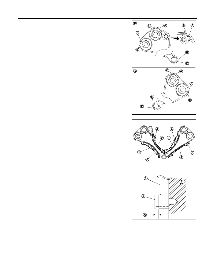
Install timing chains.

Bank 2 (F):

• Install timing chain so that the matching mark (punched) (B)

and the matching mark (outer groove) (C) on camshaft
sprocket is aligned with the copper link (A) on timing chain,
while the matching mark (punched) (B) on crankshaft sprocket
is aligned with the yellow link (D) one on timing chain, as
shown in the figure.

Bank 1 (G):

• Install timing chain so that the matching mark (punched) (B)

and the matching mark (outer groove) (C) on camshaft
sprocket is aligned with the copper link (A) on timing chain,
while the matching mark (notched) (E) on crankshaft sprocket
is aligned with the yellow link (D) one on timing chain, as
shown in the figure.

5.

Install slack guides and tension guides onto correct side by
checking with identification mark (A) on surface.

CAUTION:

Never overtighten slack guide mounting bolt (2). It is nor-
mal for a gap (A) to exist under the bolt seats when mount-
ing bolt are tightened to the specification.

6.

Install timing chain tensioner as per the following:

JPBIA3508ZZ

1

: Slack guide (bank 2)

2

: Tension guide (bank 2)

3

: Slack guide (bank 1)

4

: Tension guide (bank 1)

JPBIA3509ZZ

1

: Slack guide

3

: Cylinder block

JPBIA0117ZZ

TIMING CHAIN

EM-69

< REMOVAL AND INSTALLATION >

C

D

E

F

G

H

I

J

K

L

M

A

EM

N

P

O

a.

Fix the plunger at the most compressed position using a stopper
pin (A).
• Remove any dirt and foreign materials completely from the

back and the mounting surfaces of timing chain tensioner.

b.

Pull out stopper pin after installing, and then release plunger.

7.

Check again that the matching marks on sprockets and timing chain have not slipped out of alignment.

8.

Install oil pump and oil pump drive spacer. Refer to 

LU-13, "Exploded View"

.

9.

Install front oil seal on front cover. Refer to 

EM-96, "FRONT OIL SEAL : Removal and Installation"

.

10. Install timing chain tensioner cover (2) to front cover (1).

• Apply a continuous bead of liquid gasket with tube presser

(commercial service tool) to front cover as shown in the figure.
Use Genuine RTV silicone sealant or equivalent. Refer to

GI-22, "Recommended Chemical Products and Sealants"

.

11. Install oil filter (for valve timing control solenoid valve) (1) in the

direction shown in the figure, if removed.
• Check that the oil filter does not protrude from the upper sur-

face of front cover (2) after installation.

12. Install front cover as per the following:

a.

Install new O-ring (1), (2), (3) onto cylinder heads and cylinder
block.

JPBIA2370ZZ

a

φ

3.4 - 4.4 mm (0.134 - 0.173 in)

JPBIA2113ZZ

PBIC3260J

JPBIA3473ZZ

EM-70

< REMOVAL AND INSTALLATION >

TIMING CHAIN

b.

Apply a continuous bead of liquid gasket with tube presser
(commercial service tool) to front cover as shown in the figure.
Use Genuine RTV silicone sealant or equivalent. Refer to

GI-22, "Recommended Chemical Products and Sealants"

.

c.

Check again that the matching marks on timing chain and that
on each sprocket are aligned. Then, install front cover.

CAUTION:

Be careful not to damage front oil seal by interference with
front end of crankshaft.

d.

Tighten mounting bolts in numerical order as shown in the fig-
ure.

• There are three types of mounting bolts.

e.

After all mounting bolts are tightened, retighten them in numerical order as shown in the figure.

CAUTION:

Be sure to wipe out any excessive liquid gasket leaking onto surface mating with oil pan.

13. Install valve timing control cover as per the following:

A

: Junction between cylinder block and cylinder head

B

: Protrusion

c

: 4.3 - 5.3 mm (0.169 - 0.209 in)

d

φ

3.4 - 4.4 mm (0.134 - 0.173 in)

e

φ

4.0 - 5.6 mm (0.157 - 0.220 in)

f

φ

4.8 - 5.8 mm (0.189 - 0.228 in)

JPBIA3510ZZ

JPBIA3478ZZ

A : 0.79 in (0.79 in)

B : 1.77 in (1.77 in)

C : 3.15 in (3.15 in)

JPBIA3474ZZ

TIMING CHAIN

EM-71

< REMOVAL AND INSTALLATION >

C

D

E

F

G

H

I

J

K

L

M

A

EM

N

P

O

• Bolt (A) of fuel pump connector protector (1) cannot be

installed after installing valve timing control cover. Therefore,
install fuel pump connector protector in advance, if it is being
removed.

a.

Install new O-rings (1) on front cover.

b.

Install new seal rings (1) in shaft grooves.

CAUTION:

When replacing seal ring, replace all rings with new ones.

c.

Apply a continuous bead of liquid gasket with tube presser
(commercial service tool) to valve timing control covers as
shown in the figure.

Use Genuine RTV silicone sealant or equivalent. Refer to

GI-22, "Recommended Chemical Products and Sealants"

.

JPBIA3500ZZ

JPBIA3477ZZ

JPBIA3518ZZ

A

: Bank 1

B

: Bank 2

c

φ

3.4 - 4.4 mm (0.134 - 0.173 in)

JPBIA3519ZZ


Content   ..  655  656  657  658   ..