Infiniti QX56 (Z62). Manual - part 446


  Index      Infiniti     Infiniti QX56 (Z62) - service repair manual 2011 year


Search            


Content   ..  444  445  446  447   ..


Infiniti QX56 (Z62). Manual - part 446


DLK-250

< REMOVAL AND INSTALLATION >

KEY CYLINDER

KEY CYLINDER

GLOVE BOX LID KEY CYLINDER

GLOVE BOX LID KEY CYLINDER : Removal and Installation

INFOID:0000000006226112

REMOVAL 

1.

Remove glove box assembly. Refer to 

IP-14, "Removal and Installation"

.

2.

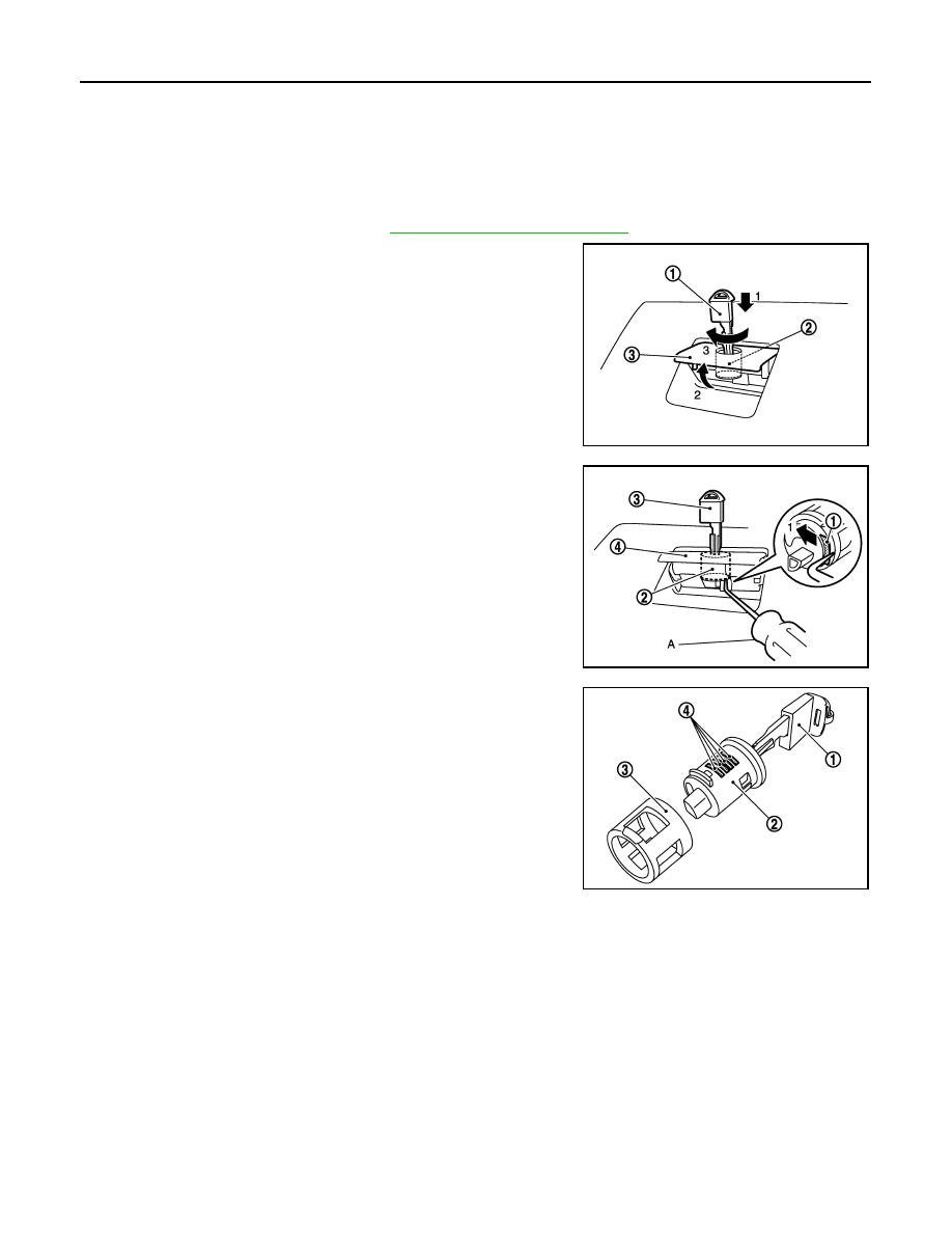
Insert mechanical key (1) into glove box lid lock cylinder (2).

3.

Set glove box lid release handle (3) to the pulled-up status.

4.

Rotate mechanical key and turn glove box lid key cylinder to the
lock position.

5.

Press tumbler stopper (1) into glove box lid lock cylinder (2)
using a hook and pick tool (A), and then remove mechanical key
(3) and glove box lid lock cylinder together from glove box lid
release handle (4).
NOTE:
When removing glove box lid lock cylinder, write a short note
describing its position against glove box lid release handle.

6.

Remove sleeve (3) from glove box lid release handle, and then
install sleeve to glove box lid lock cylinder.
NOTE:
When removing sleeve, write a short note describing its position
against glove box lid release handle.

CAUTION:

Never pull out mechanical key (1) from glove box lid lock
cylinder (2) while sleeve is uninstalled. Otherwise, tumbler
(4) pops out of glove box lid lock cylinder.

INSTALLATION 

Note the following item, and then install in the reverse order of removal.

CAUTION:

After installation, check glove box assembly open/close, lock/unlock operation.

JMKIA5490ZZ

JMKIA5491ZZ

JMKIA5819ZZ

CAB MOUNTING INSULATOR

DLK-251

< REMOVAL AND INSTALLATION >

C

D

E

F

G

H

I

J

L

M

A

B

DLK

N

O

P

CAB MOUNTING INSULATOR

Exploded View

INFOID:0000000006226113

Removal and Installation

INFOID:0000000006226114

REMOVAL

1.

Set the vehicle position for lifting body assembly using a 2-pole lift.
1.

Remove side step. Refer to 

EXT-45, "Removal and Installation"

.

2.

For replacing cab mounting insulator, separate body assembly and frame assembly. Because sepa-
rating operation lifts only body assembly, determine the vehicle position by aligning the position of
body side sill portion and arm of 2-pole lift.

CAUTION:

Never lift up by body side sill using 2-pole lift before separating body assembly from frame
assembly. Otherwise, body may be damaged.

2.

Set arm of 2-pole lift to lifting point of frame assembly. Refer to 

GI-33, "2-Pole Lift"

.

3.

Preparation.

1.

Cab mounting insulator (1st)

2.

Cab mounting insulator (2nd and 
5th)

3.

Washer

4.

Cab mounting insulator (3rd)

5.

Cab mounting insulator (4th)

6.

Frame assembly

Refer to 

GI-4, "Components"

 for symbols in the figure.

JMKIA5271GB

DLK-252

< REMOVAL AND INSTALLATION >

CAB MOUNTING INSULATOR

• Drain brake fluid from brake line. Refer to 

BR-10, "Draining"

.

• Release fuel pressure. Refer to 

EC-153, "Work Procedure"

.

• Disconnect both battery cables. Refer to 

PG-164, "Removal and Installation"

.

• Drain engine coolant from radiator. Refer to 

CO-8, "Draining"

.

• Discharge refrigerant from A/C circuit. Refer to 

HA-20, "Recycle Refrigerant"

.

• Drain power steering fluid from reservoir tank.

4.

Remove parts relating to connection of body assembly and frame assembly.
• Tire and wheel: Refer to 

WT-64, "Removal and Installation"

 (with TPMS).

• Front fender protector (LH and RH): Refer to 

EXT-23, "FENDER PROTECTOR : Removal and Installa-

tion"

.

• Front bumper: Refer to 

EXT-13, "Removal and Installation"

.

• Radiator core support upper: Refer to 

DLK-220, "Removal and Installation"

.

• Fan shroud: Refer to 

CO-16, "Removal and Installation"

.

• Battery and battery case: Refer to 

PG-164, "Removal and Installation"

.

• Air cleaner case (upper and lower): Refer to 

EM-27, "Removal and Installation"

.

• Engine cover: Refer to 

EM-25, "Removal and Installation"

.

• Rear wheel house protector (LH and RH): 

EXT-24, "REAR WHEEL HOUSE PROTECTOR : Removal

and Installation"

.

• Rear bumper: Refer to 

EXT-17, "Removal and Installation"

.

• Fuel filler tube: Remove to 

FL-8, "Exploded View"

.

• Spare tire
• Towing hook bracket.

5.

Separate parts relating to connection of body assembly and frame assembly.
Vehicle front
• Disconnect ICC sensor connector. (models with ICC) Refer to 

CCS-176, "Removal and Installation"

.

• Remove radiator upper hose and radiator lower hose from radiator assembly. Refer to 

CO-13,

"Exploded View"

.

• Remove A/T fluid cooler hose B and A/T fluid cooler hose E from A/T fluid cooler tubes. Refer to 

TM-

202, "Exploded View"

.

• Remove power steering return hose from oil cooler, and then power steering return hose clamp bolt

from frame assembly. Refer to 

ST-54, "Exploded View"

.

• Remove power steering suction hose from reservoir tank. Refer to 

ST-54, "Exploded View"

.

CAUTION:

Never spill power steering fluid in engine room.

• Remove A/C low-presser flexible hose from A/C low-presser pipe. Refer to 

HA-35, "LOW-PRESSURE

FLEXIBLE HOSE : Removal and Installation"

.

• Remove A/C hi-presser flexible hose from condenser. Refer to 

HA-34, "HIGH-PRESSURE FLEXIBLE

HOSE : Removal and Installation"

.

• Remove all engine Control Harness connectors, harness clips and others that are connected to the

body assembly side of the engine room. (engine room LH and RH side). Refer to 

PG-148, "Engine Con-

trol Harness"

.

NOTE:
Separate harness connectors from ECM (engine control module). Refer to 

EC-10, "General Precau-

tions"

.

CAUTION:

• When pulling out harnesses, never damage harnesses or connectors.
• After temporarily securing connectors, cover them with vinyl or similar material to protect

against adhesion of foreign materials.

• Disconnect engine room harness connectors and remove harness clips from engine assembly (engine

RH side). Refer to 

PG-146, "Engine Room Harness"

.

• Remove heater hoses from front water outlet tube (engine room RH side). Refer to 

HA-33, "Exploded

View"

.

• Disconnect front wheel sensor connectors (LH and RH). Refer to 

BRC-134, "FRONT WHEEL SENSOR

: Exploded View"

.

• Disconnect fuel feed tube and EVAP hose (front wheel well LH side).
• Remove steering lower shaft from steering gear side assembly. Refer to 

ST-37, "Removal and Installa-

tion"

CAUTION:

Spiral cable may be cut if steering wheel turns while separating steering column assembly and
steering gear assembly.

CAB MOUNTING INSULATOR

DLK-253

< REMOVAL AND INSTALLATION >

C

D

E

F

G

H

I

J

L

M

A

B

DLK

N

O

P

• Remove brake tube from connector (front wheel well LH and RH side). Refer to 

BR-22, "FRONT :

Exploded View"

Vehicle center side
• Remove A/T control cable from manual lever. Refer to 

TM-178, "Removal and Installation"

.

• Separate parking brake rear cable (LH and RH) from parking brake front cable. Refer to 

PB-5, "Removal

and Installation"

.

• Remove engine room harness connector (frame assembly RH center side). Refer to 

PG-146, "Engine

Room Harness"

- Remove harness connector protector.
- Disconnect chassis harness connector from engine room harness connector.
- Remove harness bracket bolt, and then remove engine room harness connector from frame assembly.
Vehicle rear side
• Remove EVAP hose (canister side).
• Remove rear final drive breather hose from air breather tube (body side). Refer to 

DLN-201, "Removal

and Installation"

.

• Disconnect body harness connector from chassis harness connectors (frame assembly LH rear side).

Refer to 

PG-150, "Body Harness"

6.

Set safety stand to frame assembly. Release arm of 2-pole lift.

7.

Remove cab mounting insulator bolts.

8.

Set arm of 2-pole lift to body side sill portion of body.

9.

Slowly lift 2-pole lift.

CAUTION:

• Check that there is no interference with the vehicle.
• Check that all connection points are disconnected.

10. Remove cab mounting insulator.

INSTALLATION

Note the following items, and then install in the reverse order of removal.

CAUTION:

• Before starting engine, check oil/fluid levels including engine coolant and engine oil. If levels are

less than the required quantity, fill to the specified level. Refer to 

MA-10, "Fluids and Lubricants"

.

• Warm up engine thoroughly to check that there is no leakage of fuel, exhaust gases, or any oil/fluids

including engine oil and engine coolant.


Content   ..  444  445  446  447   ..