Infiniti Q45. Manual - part 892


  Index      Infiniti     Infiniti Q45 - service repair manual 2006 year


Search            copyright infringement  


Content   ..  890  891  892  893   ..


Infiniti Q45. Manual - part 892


TROUBLE DIAGNOSIS FOR SYSTEM

STC-71

[WITH REAR ACTIVE STEER]

C

D

E

F

H

I

J

K

L

M

A

B

STC

5. 

CHECK (2): REAR WHEEL STEERING ANGLE SENSOR

1.

Turn ignition switch “OFF”.

2.

Disconnect rear wheel steering angle sensor harness connector.

3.

Remove rear wheel steering angle sensor.
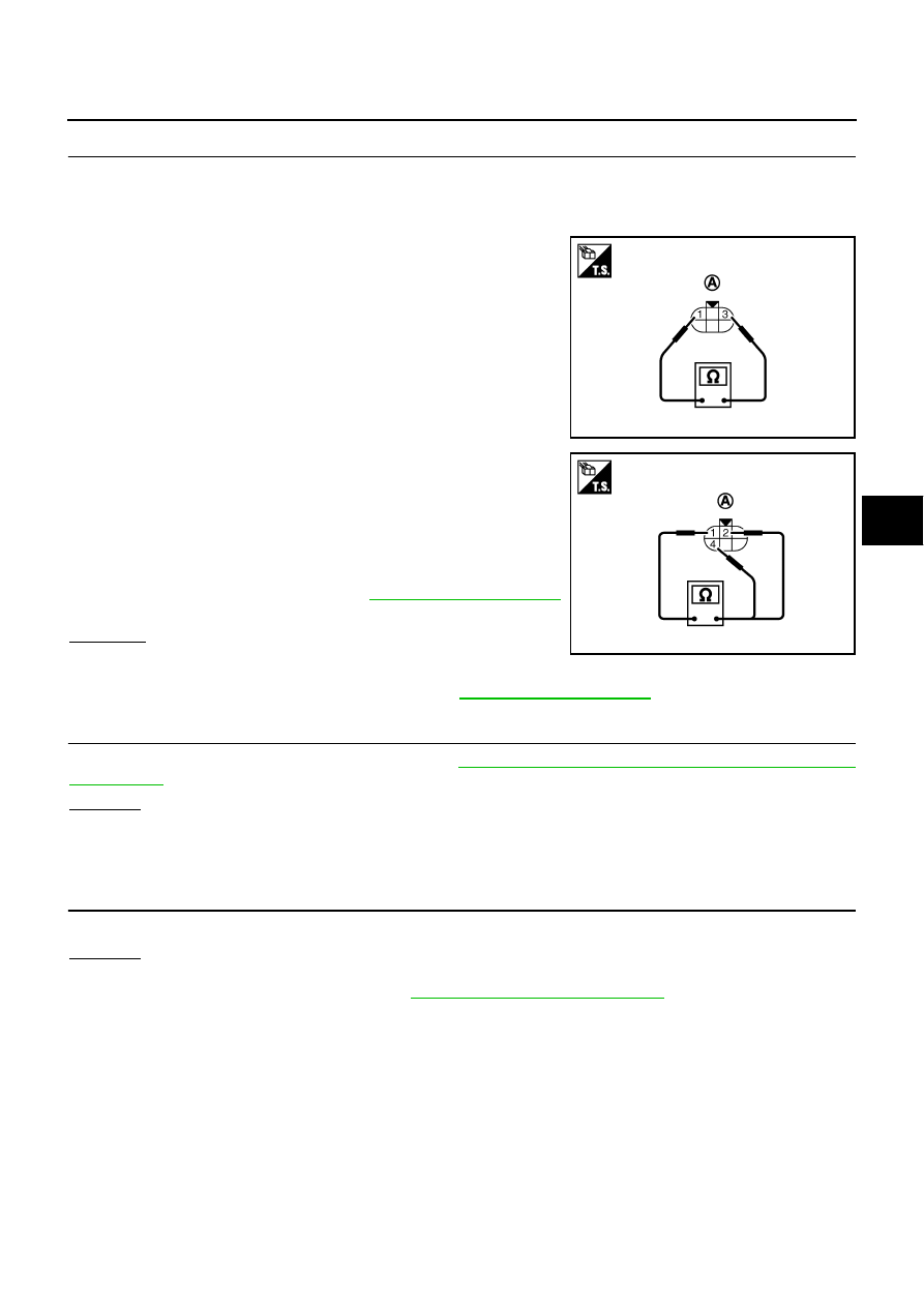
4.

Check resistance between rear wheel steering angle sensor
connector (A) B81 terminals 1 and 3.

5.

While turning the rear wheel steering angle sensor clockwise or
counterclockwise, check rear wheel steering angle sensor con-
nector (A) B81 terminals 1 and 2, 4.

6.

Perform the neutral position adjustment of rear wheel steering
angle sensor after checking. Refer to 

STC-92, "Neutral Position"

.

 OK or NG

 OK 

>> GO TO 6.

 NG

>> Replace rear wheel steering angle sensor. Perform the neutral position adjustment after replacing

rear wheel steering angle sensor. Refer to

STC-92, "Neutral Position"

 .

6. 

CHECK RAS CONTROL UNIT

Check RAS control unit input/output signal. Refer to 

STC-47, "RAS Control Unit Input/Output Signal Refer-

ence Values"

 .

OK or NG

OK

>> GO TO 7.

NG

>> Check RAS control unit pin terminals for damage or loose connection with harness connector. If

any items are damaged, repair or replace damaged parts.

7. 

CHECK DTC

Perform the self-diagnosis, after driving a vehicle for a while.

OK or NG

OK

>> INSPECTION END

NG

>> Replace RAS control unit. Refer to 

STC-90, "Removal and Installation"

 .

1 - 3

: 1 k

SGIA1485E

1 - 2

: 1.2 k – 1.5 k

1 - 4

: 1.2 k – 1.5 k

SGIA1486E

STC-72

[WITH REAR ACTIVE STEER]

TROUBLE DIAGNOSIS FOR SYSTEM

DTC C1919 VEHICLE SPEED SEN

NGS0008L

Check the following if “VEHICLE SPEED SEN [NO SIGNAL] [C1919]” is detected in self-diagnosis results
with CONSULT-II or “flickering pattern for 21” is detected in self-diagnosis results without CONSULT-II.

DIAGNOSTIC PROCEDURE

1. 

CHECK DTC WITH VDC/TCS/ABS CONTROL UNIT

Perform self-diagnosis with VDC/TCS/ABS control unit. Refer to 

BRC-24, "SELF-DIAG RESULT MODE"

 .

Is any malfunction detected by self-diagnosis?

YES

>> Check the malfunctioning system.

NO

>> GO TO 2.

2. 

CHECK RAS CONTROL SYSTEM

Perform self-diagnosis with RAS control unit. Refer to 

STC-49, "SELF-DIAG RESULT MODE"

 .

Is the “CAN COMM [U1000]” or “CONTROL UNIT (CAN) [U1010]” displayed?

YES

>> Perform trouble diagnosis for DTC U1000 CAN or DTC U1010 CONTROL UNIT (CAN). Refer to

STC-75, "DTC U1000 CAN COMM"

  or 

STC-75, "DTC U1010 CONTROL UNIT (CAN)"

 .

NO

>> GO TO 3.

3. 

CHECK RAS CONTROL UNIT

Check RAS control unit input/output signal. Refer to 

STC-47, "RAS Control Unit Input/Output Signal Refer-

ence Values"

 .

OK or NG

OK

>> GO TO 4.

NG

>> Check RAS control unit pin terminals for damage or loose connection with harness connector. If

any items are damaged, repair or replace damaged parts.

4. 

CHECK DTC

Perform the self-diagnosis, after driving a vehicle for a while.

OK or NG

OK

>> INSPECTION END

NG

>> Perform self-diagnosis with VDC/TCS/ABS control unit again. Refer to 

BRC-24, "SELF-DIAG

RESULT MODE"

 .

DTC C1920, C1923, C1924, C1926 STEERING ANGLE SEN

NGS0008M

Check the following if “STEERING ANGLE SEN [NO SIGNAL] [C1920]”, “STEERING ANGLE SEN [NO
CHANGE] [C1923]”, “STEERING ANGLE SEN [NO NEUT STATE] [C1924]” or “STEERING ANGLE SEN
[C1926]” is detected in self-diagnosis results with CONSULT-II or “flickering pattern for 22” is detected in
self-diagnosis results without CONSULT-II.

DIAGNOSTIC PROCEDURE

1. 

CHECK DTC WITH VDC/TCS/ABS CONTROL UNIT

Perform self-diagnosis with VDC/TCS/ABS control unit. Refer to 

BRC-24, "SELF-DIAG RESULT MODE"

 .

Is any malfunction detected by self-diagnosis (DTC C1158 ST ANG SEN)?

YES

>> Check the malfunctioning system.

NO

>> GO TO 2.

2. 

CHECK RAS CONTROL SYSTEM

Perform self-diagnosis with RAS control unit. Refer to 

STC-49, "SELF-DIAG RESULT MODE"

 .

Is the “CAN COMM [U1000]” or “CONTROL UNIT (CAN) [U1010]” displayed?

YES

>> Perform trouble diagnosis for DTC U1000 CAN or DTC U1010 CONTROL UNIT (CAN). Refer to

STC-75, "DTC U1000 CAN COMM"

  or 

STC-75, "DTC U1010 CONTROL UNIT (CAN)"

 .

NO

>> GO TO 3.

TROUBLE DIAGNOSIS FOR SYSTEM

STC-73

[WITH REAR ACTIVE STEER]

C

D

E

F

H

I

J

K

L

M

A

B

STC

3. 

CHECK RAS CONTROL UNIT

Check RAS control unit input/output signal. Refer to 

STC-47, "RAS Control Unit Input/Output Signal Refer-

ence Values"

 .

OK or NG

OK

>> GO TO 4.

NG

>> Check RAS control unit pin terminals for damage or loose connection with harness connector. If

any items are damaged, repair or replace damaged parts.

4. 

CHECK DTC

Perform the self-diagnosis, after driving a vehicle for a while.

OK or NG

OK

>> INSPECTION END

NG

>> Replace RAS control unit. Refer to 

STC-90, "Removal and Installation"

 .

DTC C1921 ENG REV SIGNAL

NGS0006W

Check the following if “ENG REV SIGNAL [C1921]” is detected in self-diagnosis results with CONSULT-II
or “flickering pattern for 33” is detected in self-diagnosis results without CONSULT-II.

DIAGNOSTIC PROCEDURE

1. 

CHECK DTC WITH ECM

Perform self-diagnosis with ECM. Refer to 

EC-47, "ON BOARD DIAGNOSTIC (OBD) SYSTEM"

 .

Is any malfunction detected by self-diagnosis?

YES

>> Check the malfunctioning system.

NO

>> GO TO 2.

2. 

CHECK RAS CONTROL SYSTEM

Perform self-diagnosis with RAS control unit. Refer to 

STC-49, "SELF-DIAG RESULT MODE"

 .

Is the “CAN COMM [U1000]” or “CONTROL UNIT (CAN) [U1010]” displayed?

YES

>> Perform trouble diagnosis for DTC U1000 CAN or DTC U1010 CONTROL UNIT (CAN). Refer to

STC-75, "DTC U1000 CAN COMM"

  o

STC-75, "DTC U1010 CONTROL UNIT (CAN)"

 .

NO

>> GO TO 3.

3. 

CHECK RAS CONTROL UNIT

Check RAS control unit input/output signal. Refer to 

STC-47, "RAS Control Unit Input/Output Signal Refer-

ence Values"

 .

OK or NG

OK

>> GO TO 4.

NG

>> Check RAS control unit pin terminals for damage or loose connection with harness connector. If

any items are damaged, repair or replace damaged parts.

4. 

CHECK DTC

Perform the self-diagnosis, after driving a vehicle for a while.

OK or NG

OK

>> INSPECTION END

NG

>> Perform self-diagnosis with ECM again. Refer to 

EC-47, "ON BOARD DIAGNOSTIC (OBD) SYS-

TEM"

 .

STC-74

[WITH REAR ACTIVE STEER]

TROUBLE DIAGNOSIS FOR SYSTEM

DTC C1929 VDC

NGS0008N

Check the following if “VDC [C1929]” is detected in self-diagnosis results with CONSULT-II or “flickering
pattern for 26” is detected in self-diagnosis results without CONSULT-II.

DIAGNOSTIC PROCEDURE

1. 

CHECK DTC WITH VDC/TCS/ABS CONTROL UNIT

Perform self-diagnosis with VDC/TCS/ABS control unit. Refer to 

BRC-24, "SELF-DIAG RESULT MODE"

 .

Is any malfunction detected by self-diagnosis?

YES

>> Check the malfunctioning system.

NO

>> GO TO 2.

2. 

CHECK RAS CONTROL SYSTEM

Perform self-diagnosis with RAS control unit. Refer to 

STC-49, "SELF-DIAG RESULT MODE"

 .

Is the “CAN COMM [U1000]” or “CONTROL UNIT (CAN) [U1010]” displayed?

YES

>> Perform trouble diagnosis for DTC U1000 CAN or DTC U1010 CONTROL UNIT (CAN). Refer to

STC-75, "DTC U1000 CAN COMM"

  or 

STC-75, "DTC U1010 CONTROL UNIT (CAN)"

 .

NO

>> GO TO 3.

3. 

CHECK RAS CONTROL UNIT

Check RAS control unit input/output signal. Refer to 

STC-47, "RAS Control Unit Input/Output Signal Refer-

ence Values"

 .

OK or NG

OK

>> GO TO 4.

NG

>> Check RAS control unit pin terminals for damage or loose connection with harness connector. If

any items are damaged, repair or replace damaged parts.

4. 

CHECK DTC

Perform the self-diagnosis, after driving a vehicle for a while.

OK or NG

OK

>> INSPECTION END

NG

>> Perform self-diagnosis with VDC/TCS/ABS control unit again. Refer to 

BRC-24, "SELF-DIAG

RESULT MODE"

 .


Content   ..  890  891  892  893   ..