Infiniti Q45. Manual - part 883
ELECTRICALLY CONTROLLED POWER STEERING
STC-35
[WITH REAR ACTIVE STEER]
C
D
E
F
H
I
J
K
L
M
A
B
STC
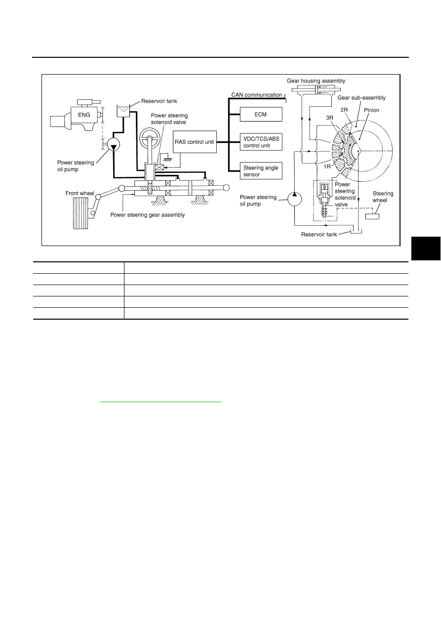
System Diagram
NGS000CO
COMPONENTS FUNCTION DESCRIPTION
CAN Communication
NGS000CP
SYSTEM DESCRIPTION
CAN (Controller Area Network) is a serial communication line for real time application. It is an on-vehicle mul-
tiplex communication line with high data communication speed and excellent error detection ability. Many elec-
tronic control units are equipped onto a vehicle, and each control unit shares information and links with other
control units during operation (not independent). In CAN communication, control units are connected with 2
communication lines (CAN-H line, CAN-L line) allowing a high rate of information transmission with less wiring.
Each control unit transmits/receives data but selectively reads required data only.
For details, refer to
SGIA1446E
Component parts
Function
RAS control unit
Controls power steering solenoid valve (with fail-safe function).
Power steering solenoid valve
Controls oil pressure in gear housing assembly.
VDC/TCS/ABS control unit
Transmits vehicle speed signal via CAN communication to RAS control unit. (For fail-safe conditions)
ECM
Transmits engine speed signal via CAN communication to RAS control unit.