Infiniti Q45. Manual - part 881


  Index      Infiniti     Infiniti Q45 - service repair manual 2006 year


Search            copyright infringement  


Content   ..  879  880  881  882   ..


Infiniti Q45. Manual - part 881


TROUBLE DIAGNOSIS FOR SYSTEM

STC-27

[WITHOUT REAR ACTIVE STEER]

C

D

E

F

H

I

J

K

L

M

A

B

STC

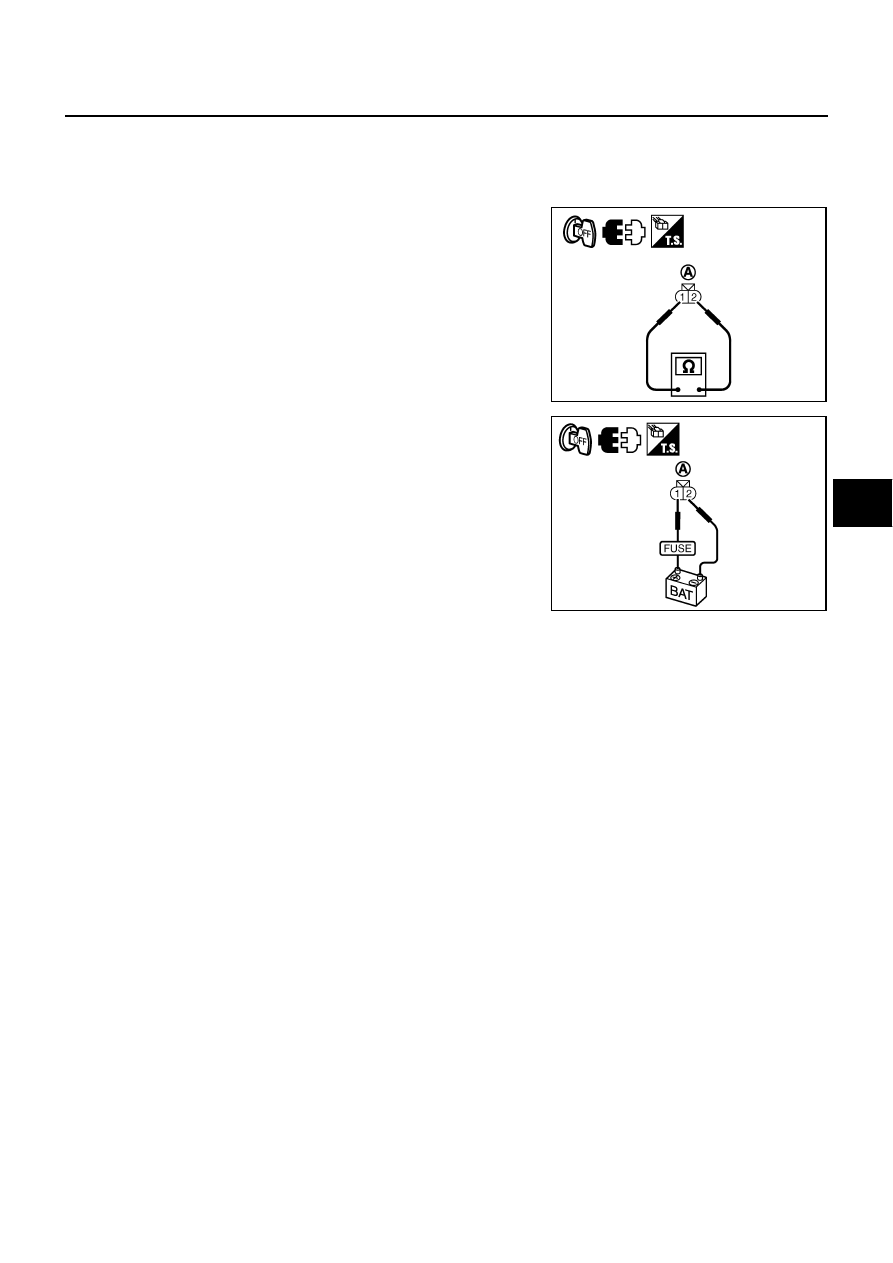
Component Inspection

NGS000CT

POWER STEERING SOLENOID VALVE

1.

Turn ignition switch “OFF”.

2.

Disconnect power steering solenoid valve harness connector.

3.

Check resistance between power steering solenoid valve con-
nector (A) terminals 1 and 2.

4.

Check power steering solenoid valve connector (A) by listening
for its operation sound while applying battery voltage to power
steering solenoid valve connector (A) terminals 1 (positive) and
2 (negative).

5.

If NG, replace power steering solenoid valve.

1 - 2

: Approx. 4 - 6 

SGIA1412E

SGIA1419E

STC-28

[WITHOUT REAR ACTIVE STEER]

TROUBLE DIAGNOSIS FOR SYMPTOMS

TROUBLE DIAGNOSIS FOR SYMPTOMS

PFP:00007

Hard Steering When Fully Turning the Steering Wheel

NGS0006F

DIAGNOSTIC PROCEDURE

1. 

CHECK SELF-DIAGNOSTIC RESULTS

Perform self-diagnosis. Refer to 

STC-13, "SELF-DIAG RESULT MODE"

 .

Is any malfunction detected by self-diagnosis?

YES

>> Check the malfunctioning system.

NO

>> GO TO 2.

2. 

CHECK SYSTEM FOR VEHICLE SPEED SENSOR

Perform trouble diagnosis for vehicle speed sensor system. Refer to 

STC-19, "Vehicle Speed Sensor (VEHI-

CLE SPEED SEN)"

 .

OK or NG

OK

>> GO TO 3.

NG

>> Repair or replace damaged parts.

3. 

CHECK SYSTEM FOR POWER STEERING SOLENOID VALVE

Perform trouble diagnosis for power steering solenoid valve system. Refer to 

STC-21, "Power Steering Sole-

noid Valve"

 .

OK or NG

OK

>> GO TO 4.

NG

>> Repair or replace damaged parts.

4. 

CHECK ACTIVE DAMPER SUSPENSION CONTROL UNIT

Check active damper suspension control unit input/output signal. Refer to 

STC-12, "Active Damper Suspen-

sion Control Unit Input/Output Signal Reference Values"

 .

OK or NG

OK

>> GO TO 5.

NG

>> Check active damper suspension control unit pin terminals for damage or loose connection with

harness connector. If any items are damaged, repair or replace damaged parts.

5. 

CHECK SYMPTOM

Check again.

OK or NG

OK

>> INSPECTION END

NG

>> Replace active damper suspension control unit. Refer to 

STC-30, "Removal and Installation"

 .

TROUBLE DIAGNOSIS FOR SYMPTOMS

STC-29

[WITHOUT REAR ACTIVE STEER]

C

D

E

F

H

I

J

K

L

M

A

B

STC

Light Steering When Driving at a High Speed

NGS0006G

DIAGNOSTIC PROCEDURE

1. 

CHECK SELF-DIAGNOSTIC RESULTS

Perform self-diagnosis. Refer to 

STC-13, "SELF-DIAG RESULT MODE"

 .

Is any malfunction detected by self-diagnosis?

YES

>> Check the malfunctioning system.

NO

>> GO TO 2.

2. 

CHECK SYSTEM FOR VEHICLE SPEED SENSOR

Perform trouble diagnosis for vehicle speed sensor system. Refer to 

STC-19, "Vehicle Speed Sensor (VEHI-

CLE SPEED SEN)"

 .

OK or NG

OK

>> GO TO 3.

NG

>> Repair or replace damaged parts.

3. 

CHECK SYSTEM FOR POWER STEERING SOLENOID VALVE

Perform trouble diagnosis for power steering solenoid valve system. Refer to 

STC-21, "Power Steering Sole-

noid Valve"

 .

OK or NG

OK

>> GO TO 4.

NG

>> Repair or replace damaged parts.

4. 

CHECK ACTIVE DAMPER SUSPENSION CONTROL UNIT

Check active damper suspension control unit input/output signal. Refer to 

STC-12, "Active Damper Suspen-

sion Control Unit Input/Output Signal Reference Values"

 .

OK or NG

OK

>> GO TO 5.

NG

>> Check active damper suspension control unit pin terminals for damage or loose connection with

harness connector. If any items are damaged, repair or replace damaged parts.

5. 

CHECK SYMPTOM

Check again.

OK or NG

OK

>> INSPECTION END

NG

>> Replace active damper suspension control unit. Refer to 

STC-30, "Removal and Installation"

 .

STC-30

[WITHOUT REAR ACTIVE STEER]

CONTROL UNIT

CONTROL UNIT

PFP:28400

Removal and Installation

NGS0005R

REMOVAL

1.

Turn the ignition switch OFF and disconnect the battery cable from the negative terminal.

2.

Remove the trunk side finisher. Refer to 

EI-60, "Removal and Installation"

 .

3.

Disconnect the two active damper suspension control unit con-
nectors.

4.

Remove the active damper suspension control unit bolts.

5.

Remove the active damper suspension control unit (1).

INSTALLATION

Note the following, and installation is the reverse order of removal.

When installing the active damper suspension control unit, tighten bolts to the specified torque.

SGIA1423E

Active damper suspension control unit bolts

: 8.3 N·m (0.85 kg-m, 73 in-lb)


Content   ..  879  880  881  882   ..