Infiniti Q45. Manual - part 882
PRECAUTIONS
STC-31
[WITH REAR ACTIVE STEER]
C
D
E
F
H
I
J
K
L
M
A
B
STC
[WITH REAR ACTIVE STEER]
PRECAUTIONS
PFP:00001
Precautions for Supplemental Restraint System (SRS) “AIR BAG” and “SEAT
BELT PRE-TENSIONER”
NGS0006I
The Supplemental Restraint System such as “AIR BAG” and “SEAT BELT PRE-TENSIONER”, used along
with a front seat belt, helps to reduce the risk or severity of injury to the driver and front passenger for certain
types of collision. This system includes seat belt switch inputs and dual stage front air bag modules. The SRS
system uses the seat belt switches to determine the front air bag deployment, and may only deploy one front
air bag, depending on the severity of a collision and whether the front occupants are belted or unbelted.
Information necessary to service the system safely is included in the SRS and SB section of this Service Man-
ual.
WARNING:
●
To avoid rendering the SRS inoperative, which could increase the risk of personal injury or death
in the event of a collision which would result in air bag inflation, all maintenance must be per-
formed by an authorized NISSAN/INFINITI dealer.
●
Improper maintenance, including incorrect removal and installation of the SRS, can lead to per-
sonal injury caused by unintentional activation of the system. For removal of Spiral Cable and Air
Bag Module, see the SRS section.
●
Do not use electrical test equipment on any circuit related to the SRS unless instructed to in this
Service Manual. SRS wiring harnesses can be identified by yellow and/or orange harnesses or
harness connectors.
Precautions
NGS0006J
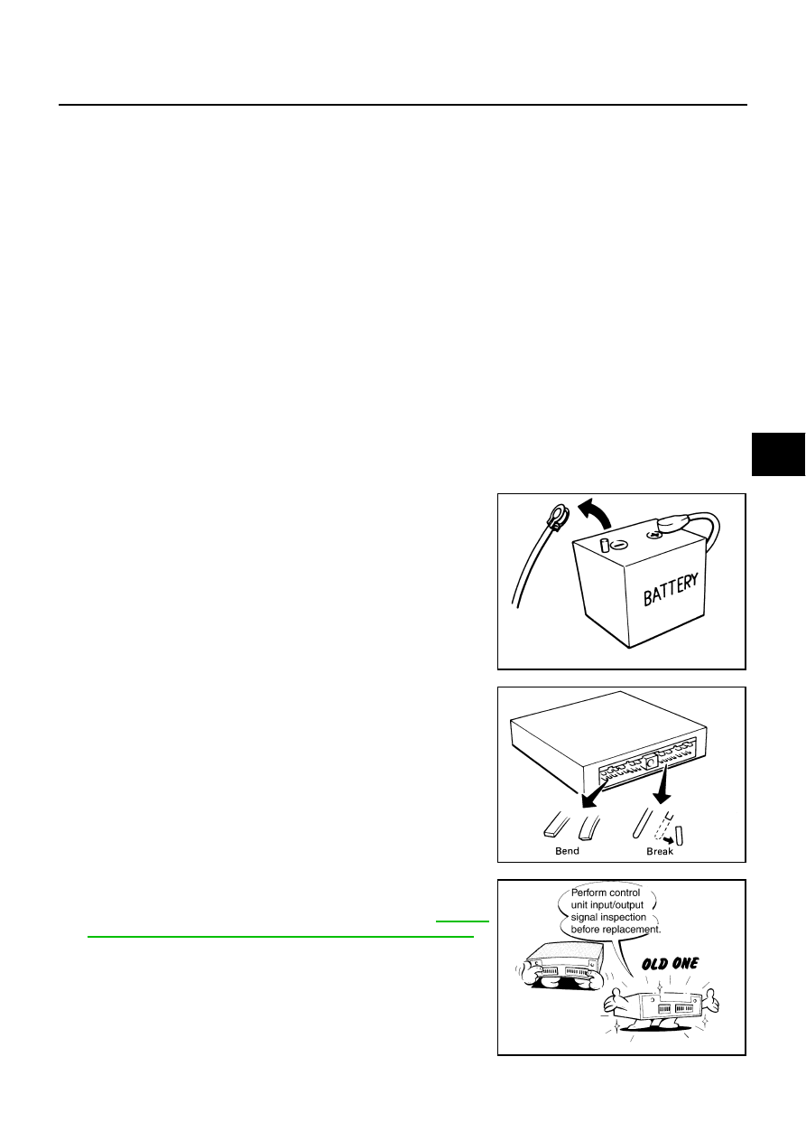
●
Before connecting or disconnecting the RAS control unit
harness connector, turn ignition switch “OFF” and discon-
nect the battery cable from the negative terminal. Battery
voltage is applied to RAS control unit even if ignition switch
is turned “OFF”.
●
When connecting or disconnecting pin connectors into or
from RAS control unit, take care not to damage pin termi-
nals (bend or break).
When connecting pin connectors make sure that there are
not any bends or breaks on RAS control unit pin terminals.
●
Before replacing RAS control unit, perform RAS control
unit input/output signal inspection and make sure whether
RAS control unit functions properly or not. Refer to
"RAS Control Unit Input/Output Signal Reference Values"
SEF289H
SEF291H
SDIA1848E