Infiniti Q45. Manual - part 862
SUPPLEMENTAL RESTRAINT SYSTEM (SRS)
SRS-5
C
D
E
F
G
I
J
K
L
M
A
B
SRS
SUPPLEMENTAL RESTRAINT SYSTEM (SRS)
PFP:28556
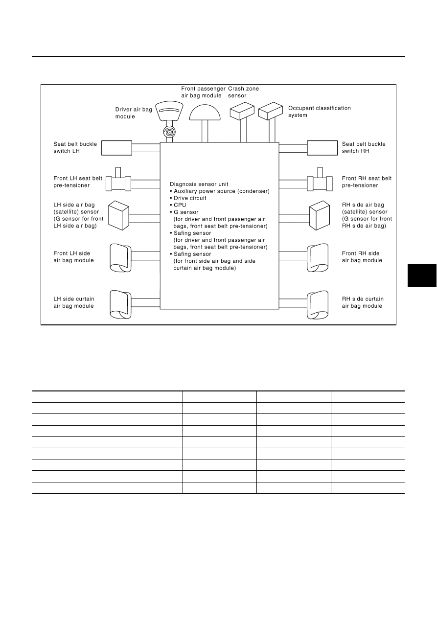
SRS Configuration
NHS00049
The air bag deploys if the diagnosis sensor unit activates while the ignition switch is in the ON or START posi-
tion.
The collision modes for which supplemental restraint systems are activated are different among the SRS sys-
tems. For example, the driver air bag module and front passenger air bag module are activated in a frontal col-
lision but not in a side collision.
SRS configurations which are activated for some collision modes are as follows;
PHIA1120E
SRS configuration
Frontal collision
Left side collision
Right side collision
Driver air bag module
×
—
—
Front passenger air bag module
×
—
—
Front LH seat belt pre-tensioner
×
—
—
Front RH seat belt pre-tensioner
×
—
—
Front LH side air bag module
—
×
—
Front RH side air bag module
—
—
×
LH side curtain air bag module
—
×
—
RH side curtain air bag module
—
—
×