Infiniti Q45. Manual - part 860
REAR SEAT
SE-195
C
D
E
F
G
H
J
K
L
M
A
B
SE
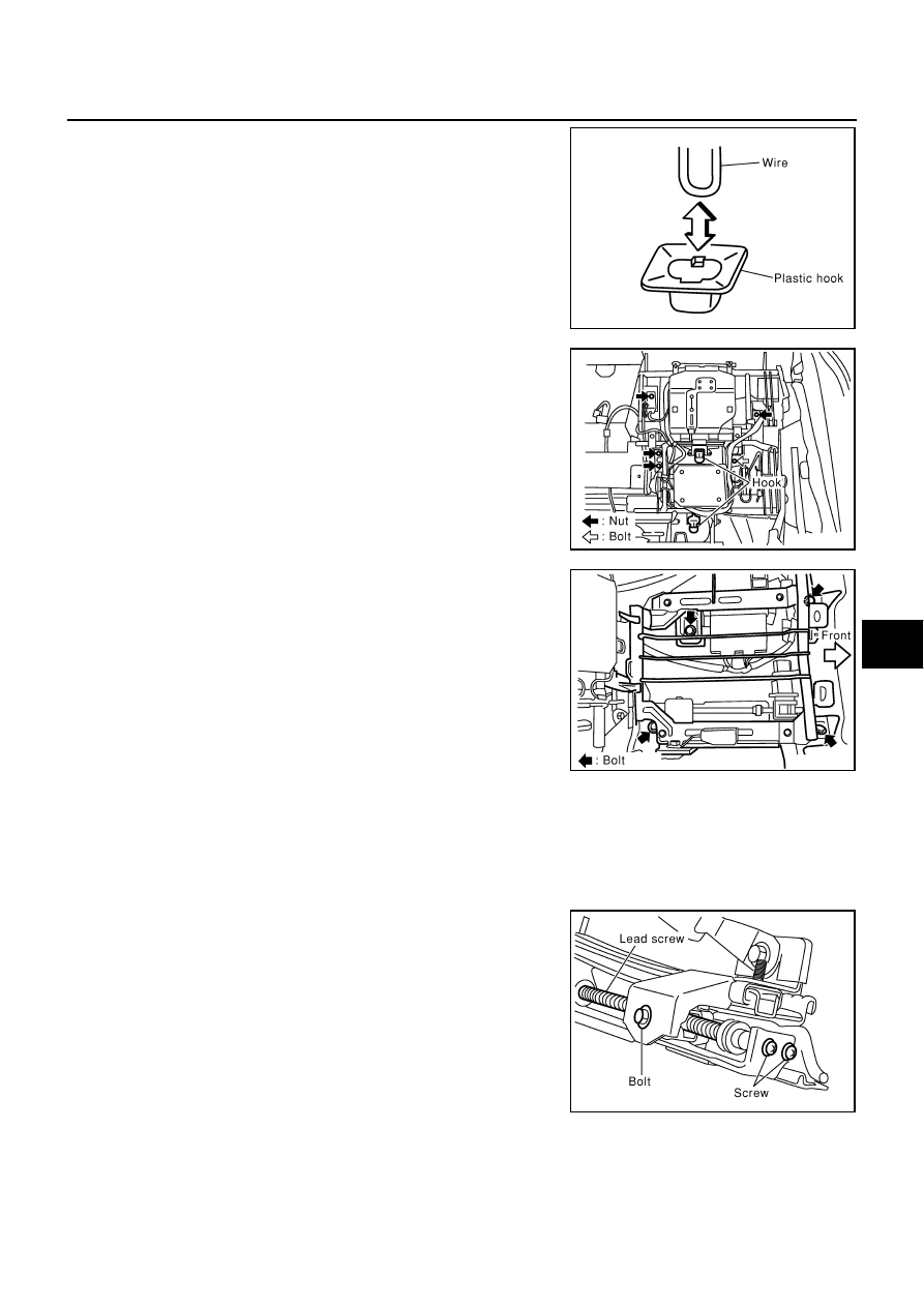
2.
Raise the bottom of the seat cushion to release the wire from the
plastic hook then pull the seat cushion forward to remove. (For
the LH seat, disconnect the harness connector for the seat
heater).
3.
Access the hooks from between the seatback pad and rear seat-
back frame, and pull them downward to remove the wire. Then,
slide the seatback upward to remove.
4.
Remove nuts and bolts to remove the power unit frame assem-
bly.
5.
Remove the mounting bolts and disconnect the vehicle-side har-
ness connector on the seat cushion frame.
6.
After removing, remove the hog ring to separate the trim and pad, and rear seat heater unit (only LH-side).
INSTALLATION OF POWER SEAT (SPLIT SEAT)
Install in the reverse order of removal.
Disassembly and Assembly
NIS0015M
DISASSEMBLY OF SLIDING MOTOR & UNIT
1.
Remove mounting bolts and screws on the lead screw unit.
SIIA0517E
SIIA0515E
SIIA0519E
SIIA0522E