Infiniti Q45. Manual - part 559
 

  Index      Infiniti     Infiniti Q45 - service repair manual 2006 year


Search            copyright infringement  


Content   ..  557  558  559  560   ..


Infiniti Q45. Manual - part 559


CAMSHAFT

EM-53

C

D

E

F

G

H

I

J

K

L

M

A

EM

●

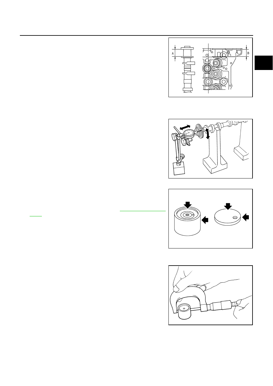
Measure the following parts if out of the standard.

–

Dimension “A” for camshaft No. 1 journal

–

Dimension “B” for cylinder head No. 1 journal

●

Refer to the standards above, and then replace camshaft and/
or cylinder head.

Camshaft Sprocket Runout

1.

Put V-block on precise flat table, and support No. 2 and No. 5 journal of camshaft.

CAUTION:

Do not support journal No. 1 (on the side of camshaft
sprocket) because it has a different diameter from the other
four locations.

2.

Measure camshaft sprocket runout with a dial indicator (total
indicator reading).

●

If it exceeds the limit, replace camshaft sprocket.

Valve Lifter and Adjusting Shim

Check if surface of valve lifter and adjusting shim has any wear or
cracks.

●

If anything above is found, replace valve lifter or adjusting shim. 

●

When replacing adjusting shim. Refer to 

EM-57, "Valve Clear-

ance"

 .

Valve Lifter Clearance

VALVE LIFTER OUTER DIAMETER

●

Measure outer diameter of valve lifter with a micrometer.

Standard

: 30.500 - 30.548 mm (1.2008 - 1.2027 in)

Standard

: 30.360 - 30.385 mm (1.1953 - 1.1963 in)

KBIA2426J

Limit

: 0.15 mm (0.0059 in)

PBIC0930E

PBIC0231E

Standard: 33.965 - 33.975 mm (1.3372 - 1.3376 in)

SEM961E

EM-54

CAMSHAFT

VALVE LIFTER HOLE DIAMETER

●

Measure inner diameter of valve lifter hole of cylinder head with
an inside micrometer.

VALVE LIFTER CLEARANCE

●

(Valve lifter clearance) = (valve lifter hole diameter) – (valve lifter outer diameter)

●

If out of the standard, referring to each standard of valve lifter outer diameter and valve lifter hole diame-
ter, replace either or both valve lifter and cylinder head.

INSTALLATION

1.

Install adjusting shims and valve lifters if necessary.

●

Install removed parts in the same locations as before.

2.

Install camshafts. Refer to the table below for identification of
right and left bank, and intake and exhaust.

●

Install so that dowel pin at the front of camshaft face is in the
direction shown in the figure. (No.1 cylinder at compression
TDC)

Standard:

34.000 - 34.016 mm (1.3386 - 1.3392 in)

PBIC0043E

Standard:

0.025 - 0.051 mm (0.0010 - 0.0020 in)

Bank

INT/EXH

Identifica-

tion paint 

(front)

Identifica-

tion paint 

(rear)

Identifica-

tion rib

Inscribed 

symbol

Left

INT

Blue

—

No

LH

EXH

—

Orange

No

LH

Right

INT

Blue

—

Yes

RH

EXH

—

Orange

Yes

RH

Camshaft dowel pin

: At cylinder head upper face side in each bank

PBIC0032E

SBIA0366E

CAMSHAFT

EM-55

C

D

E

F

G

H

I

J

K

L

M

A

EM

3.

Install camshaft brackets as follows:

●

Remove foreign material completely from camshaft bracket
backside and from cylinder head installation face.

●

Install by referring to installation location mark on upper sur-
face and front mark.

●

Install so that installation location mark can be correctly read
when viewed from the side of left exhaust bank.

●

Apply liquid gasket to camshaft bracket (No.1) as in the fig-
ure.
Use Genuine RTV Silicone Sealant or equivalent. Refer to

GI-45, "RECOMMENDED CHEMICAL PRODUCTS AND
SEALANTS"

 .

CAUTION:

●

After installation, be sure to wipe off any excessive liq-
uid gasket leaking from part “A” and “B”(both on right
and left sides).

●

Remove completely any excess of liquid gasket inside
bracket. 

●

Apply liquid gasket to camshaft bracket (INT,No.6) on left
bank intake as in the illustration.

CAUTION:

●

After installation, be sure to wipe off any excessive liq-
uid gasket leaking from part “A”, and “ B”(both on
right and left sides).

●

Remove completely any excess of liquid gasket inside
bracket. 

PBIC0034E

PBIC2356E

PBIC2357E

EM-56

CAMSHAFT

4.

Tighten camshaft bracket bolts in the following steps, in numeri-
cal order as shown in the figure.

a.

Tighten No. 9 to 12 in numerical order as shown.

b.

Tighten No. 1 to 8 in numerical order as shown.

c.

Tighten No. 13 to 14 in numerical order as shown. (Left bank
only)

d.

Tighten all bolts in numerical order as shown.

e.

Tighten No. 1 to 12 in numerical order as shown.

f.

Tighten No. 13 to 14 in numerical order as shown. (Left bank
only)

CAUTION:

After tightening mounting bolts of camshaft brackets, be sure to wipe off excessive liquid gasket
from the parts listed below. 

●

Mating surface of rocker cover 

●

Mating surface of camshaft bracket (INT,No.6) on left bank.

●

Mating surface of front cover

5.

Install camshaft sprockets.

●

Install by checking with identification mark on surface.

●

Install camshaft sprocket (EXH) by selectively using the
groove of dowel pin according to the bank. (Common part
used for both banks.)

●

Lock the hexagonal part of camshaft in the same way as for
removal, and tighten mounting bolts.

6.

Check and adjust valve clearances. Refer to 

EM-57, "Valve Clearance"

 .

7.

Install in the reverse order of removal.

INSPECTION AFTER INSTALLATION
Inspection of Camshaft Sprocket (INT) Oil Groove

CAUTION:

●

Perform this inspection only when DTC P0011 and/or P0021 are detected in self-diagnostic results
of CONSULT-II and it is directed according to inspection procedure of EC section. Refer to 

EC-82,

"TROUBLE DIAGNOSIS"

  .

●

Check when the engine is cold so as to prevent burns from any splashing engine oil.

1.

Check the engine oil level. Refer to 

LU-6, "ENGINE OIL"

  .

2.

Perform the following procedure so as to prevent the engine from being unintentionally started while
checking.

a.

Release fuel pressure. Refer to 

EC-80, "FUEL PRESSURE RELEASE"

  .

b.

Disconnect ignition coil and injector harness connectors.

: 2.0 N·m (0.2 kg-m, 1 ft-lb)

: 2.0 N·m (0.2 kg-m, 1 ft-lb)

: 2.0 N·m (0.2 kg-m, 1 ft-lb)

: 5.9 N·m (0.6 kg-m, 4 ft-lb)

: 10.4 N·m (1.1 kg-m, 8 ft-lb)

: 31.4 N·m (3.2 kg-m, 23 ft-lb)

PBIC0031E

PBIC2345E


Content   ..  557  558  559  560   ..