Infiniti Q45. Manual - part 558


  Index      Infiniti     Infiniti Q45 - service repair manual 2006 year


Search            copyright infringement  


Content   ..  556  557  558  559   ..


Infiniti Q45. Manual - part 558


TIMING CHAIN

EM-49

C

D

E

F

G

H

I

J

K

L

M

A

EM

c.

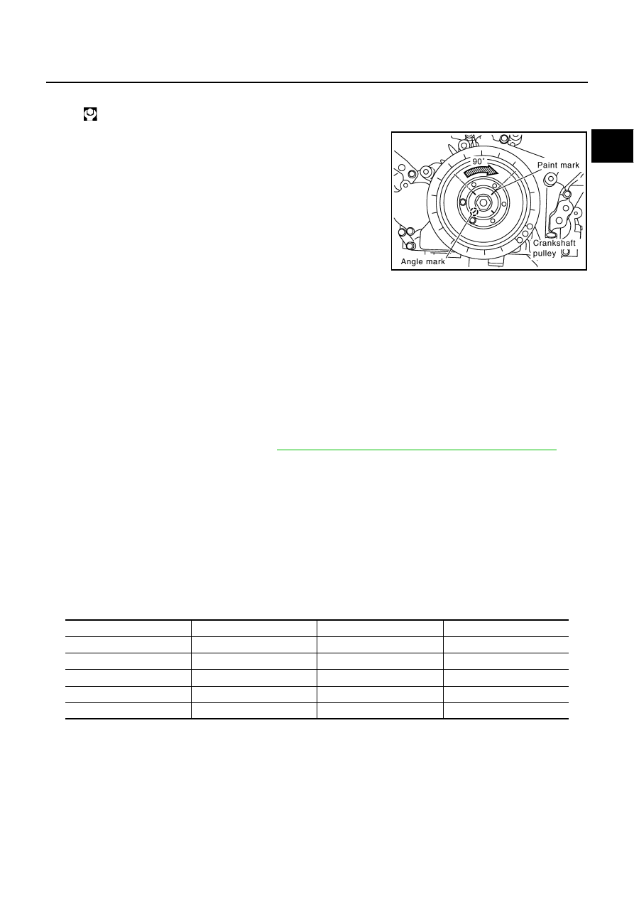
Tighten bolt crankshaft pulley bolt.

d.

Select one most visible notch of the four on bolt flange. Corre-
sponding to the selected notch, put a mating mark (such as
paint) on crankshaft pulley. 

e.

Tighten further by 90 degrees. (Angle tightening)

Check the tightening angle by referencing to the notches. The
angle between two notches is 90 degrees.

15. Rotate crankshaft pulley in normal direction (clockwise when viewed from engine front) to check for inter-

ference among parts.

16. Install in the reverse order of removal.

NOTE:
If hydraulic pressure inside timing chain tensioner drops after removal/installation, slack in guide may gen-
erate a pounding noise during and just after engine start. However, this does not indicate an unusualness.
Noise will stop after hydraulic pressure rises.

INSPECTION AFTER INSTALLATION
Inspection for Leaks

The following are procedures for checking fluids leak, lubricates leak and exhaust gases leak.

Before starting engine, check oil/fluid levels including engine coolant and engine oil. If less than required
quantity, fill to the specified level. Refer to 

MA-10, "RECOMMENDED FLUIDS AND LUBRICANTS"

 .

Use procedure below to check for fuel leakage.

Turn ignition switch “ON” (with engine stopped). With fuel pressure applied to fuel piping, check for fuel
leakage at connection points.

Start engine. With engine speed increased, check again for fuel leakage at connection points.

Run engine to check for unusual noise and vibration.

Warm up engine thoroughly to make sure there is no leakage of fuel, exhaust gas, or any oils/fluids includ-
ing engine oil and engine coolant.

Bleed air from passages in lines and hoses, such as in cooling system.

After cooling down engine, again check oil/fluid levels including engine oil and engine coolant. Refill to
specified level, if necessary.

Summary of the inspection items:

* Transmission/transaxle/CVT fluid, power steering fluid, brake fluid, etc.

: 93.1 N·m (9.5 kg-m, 69 ft-lb).

PBIC2346E

Item

Before starting engine

Engine running

After engine stopped

Engine coolant

Level

Leakage

Level

Engine oil

Level

Leakage

Level

Other oils and fluids *

Level

Leakage

Level

Fuel

Leakage

Leakage

Leakage 

Exhaust gas

Leakage

EM-50

CAMSHAFT

CAMSHAFT

PFP:13001

Removal and Installation

NBS001OS

REMOVAL

1.

Remove timing chain. Refer to 

EM-39, "Removal and Installation"

 .

2.

With hexagonal part of camshaft locked with wrench, loosen
bolts securing camshaft sprocket to remove camshaft sprocket. 

CAUTION:

To avoid interference between valves and pistons, do not
turn crankshaft or camshaft with timing chain discon-
nected.

1.

Cylinder head (right bank)

2.

Camshaft bracket (No. 2, 3, 4, 5)

3.

Adjusting shim

4.

Valve lifter

5.

Camshaft bracket (No. 1)

6.

Washer

7.

Camshaft (EXH)

8.

Camshaft sprocket (EXH)

9.

Camshaft sprocket (INT)

10.

Camshaft (INT)

11.

Cylinder head (left bank)

12.

Adjusting shim

13.

Valve lifter

14.

Camshaft (INT)

15.

Camshaft sprocket (INT)

16.

Camshaft sprocket (EXH)

17.

Camshaft (EXH)

18.

Camshaft bracket (No.1)

19.

Washer

20.

Camshaft bracket (No. 2, 3, 4, 5)

21.

Camshaft bracket (INT, No. 6)

22.

Bracket

PBIC4127E

PBIC0030E

CAMSHAFT

EM-51

C

D

E

F

G

H

I

J

K

L

M

A

EM

3.

Loosen fixing bolts in the reverse order of that shown in the fig-
ure to remove camshaft brackets. 

Lightly tapping with plastic hammer, remove No. 1 camshaft
bracket and No. 6 camshaft bracket. 
NOTE:
The bottom surface of each bracket will be stuck to cylinder
head because of liquid gasket.

4.

Remove camshaft.

5.

Remove adjusting shims and valve lifters if necessary.

Correctly identify location where each part is installed. Keep parts in an organized way to avoid mixing
them up.

INSPECTION AFTER REMOVAL
Camshaft Runout

1.

Put V block on precise flat bed, and support No. 2 and No. 5
journal of camshaft.

CAUTION:

Do not support journal No.1 (on the side of camshaft
sprocket) because it has a different diameter from the other
four locations.

2.

Set a dial indicator vertically to No.3 journal.

3.

Turn camshaft to one direction with hands, and measure cam-
shaft runout on a dial indicator. (Total indicator reading)

If it exceeds the limit, replace camshaft.

Camshaft Cam Height

Measure camshaft cam height.

If it exceeds the limit, replace camshaft.

PBIC0031E

Limit

: 0.02 mm (0.0008 in)

PBIC2499E

Standard:

Intake

: 44.865 - 45.055 mm (1.7663 - 1.7738 in)

Exhaust

: 43.925 - 44.115 mm (1.7293 - 1.7368 in)

Cam wear

limit

: 0.2 mm (0.008 in)

PBIC0039E

EM-52

CAMSHAFT

Camshaft Journal Oil Clearance

CAMSHAFT JOURNAL OUTER DIAMETER

Measure outer diameter of camshaft journal with a micrometer.

CAMSHAFT BRACKET INNER DIAMETER

Tighten camshaft bracket bolt with specified torque. Refer to

EM-54, "INSTALLATION"

  for the tightening procedure.

Measure the inner diameter “A” of camshaft bracket with an
inside micrometer.

CAMSHAFT JOURNAL OIL CLEARANCE

(Journal oil clearance) = (Camshaft bracket inner diameter) – (Camshaft journal outer diameter)

If out of the standard, replace either or both camshaft and cylinder head.

NOTE:
It is impossible to replace only camshaft bracket as camshaft bracket is manufactured with cylinder head.
Replace the whole cylinder head assembly.

Camshaft End Play

1.

Install camshaft in cylinder head. Refer to 

EM-54, "INSTALLATION"

  for tightening procedure.

2.

Install a dial indicator in thrust direction on front end of camshaft.
Measure the camshaft end play when camshaft is moved for-
ward/backward (in direction to axis).

Standard:

No. 1

: 25.938 - 25.955 mm (1.0212 - 1.0218 in)

No. 2, 3, 4, 5

: 25.953 - 25.970 mm (1.0218 - 1.0224 in)

PBIC0040E

Standard:

26.000 - 26.021 mm (1.0236 - 1.0244 in)

PBIC1645E

Standard:

No. 1

: 0.045 - 0.083 mm (0.0018 - 0.0033 in)

No. 2, 3, 4, 5

: 0.030 - 0.068 mm (0.0012 - 0.0027 in)

Standard:

0.115 - 0.188 mm (0.0045 - 0.0074 in)

PBIC2446E


Content   ..  556  557  558  559   ..