Infiniti M45 (Y34). Manual - part 444
DTC P1140, P1145 IVT CONTROL POSITION SENSOR
EC-465
C
D
E
F
G
H
I
J
K
L
M
A
EC
2.
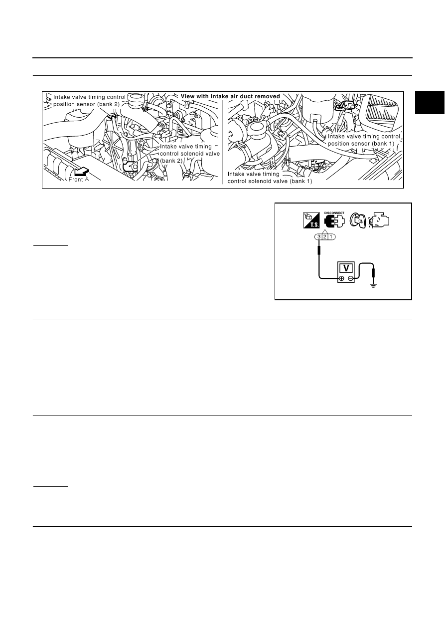
CHECK INTAKE VALVE TIMING CONTROL POSITION SENSOR POWER SUPPLY CIRCUIT
1.
Disconnect intake valve timing control position sensor harness connector.
2.
Turn ignition switch ON.
3.
Check voltage between intake valve timing control position sen-
sor terminal 3 and ground with CONSULT-II or tester.
OK or NG
OK
>> GO TO 4.
NG
>> GO TO 3.
3.
DETECT MALFUNCTIONING PART
Check the following.
●
Harness connectors M135, F105
●
Harness for open or short between intake valve timing control position sensor and ECM
●
Harness for open or short between intake valve timing control position sensor and ECM relay
>> Repair harness or connectors.
4.
CHECK INTAKE VALVE TIMING CONTROL POSITION SENSOR GROUND CIRCUIT FOR OPEN AND
SHORT
1.
Turn ignition switch OFF.
2.
Check harness continuity between intake valve timing control position sensor terminal 1 and ground.
Refer to Wiring Diagram.
3.
Also check harness for short to power.
OK or NG
OK
>> GO TO 6.
NG
>> GO TO 5.
5.
DETECT MALFUNCTIONING PART
Check the following.
●
Joint connector-29
●
Harness for open or short between intake valve timing control position sensor and ground
>> Repair open circuit or short to power in harness or connectors.
Voltage: Battery voltage
PBIB1115E
SEF509Y
Continuity should exist.