Infiniti M45 (Y34). Manual - part 442


  Index      Infiniti     Infiniti M45 (Y34) - service repair manual 2004 year


Search            copyright infringement  


Content   ..  440  441  442  443   ..


Infiniti M45 (Y34). Manual - part 442


DTC P1128 THROTTLE CONTROL MOTOR

EC-457

C

D

E

F

G

H

I

J

K

L

M

A

EC

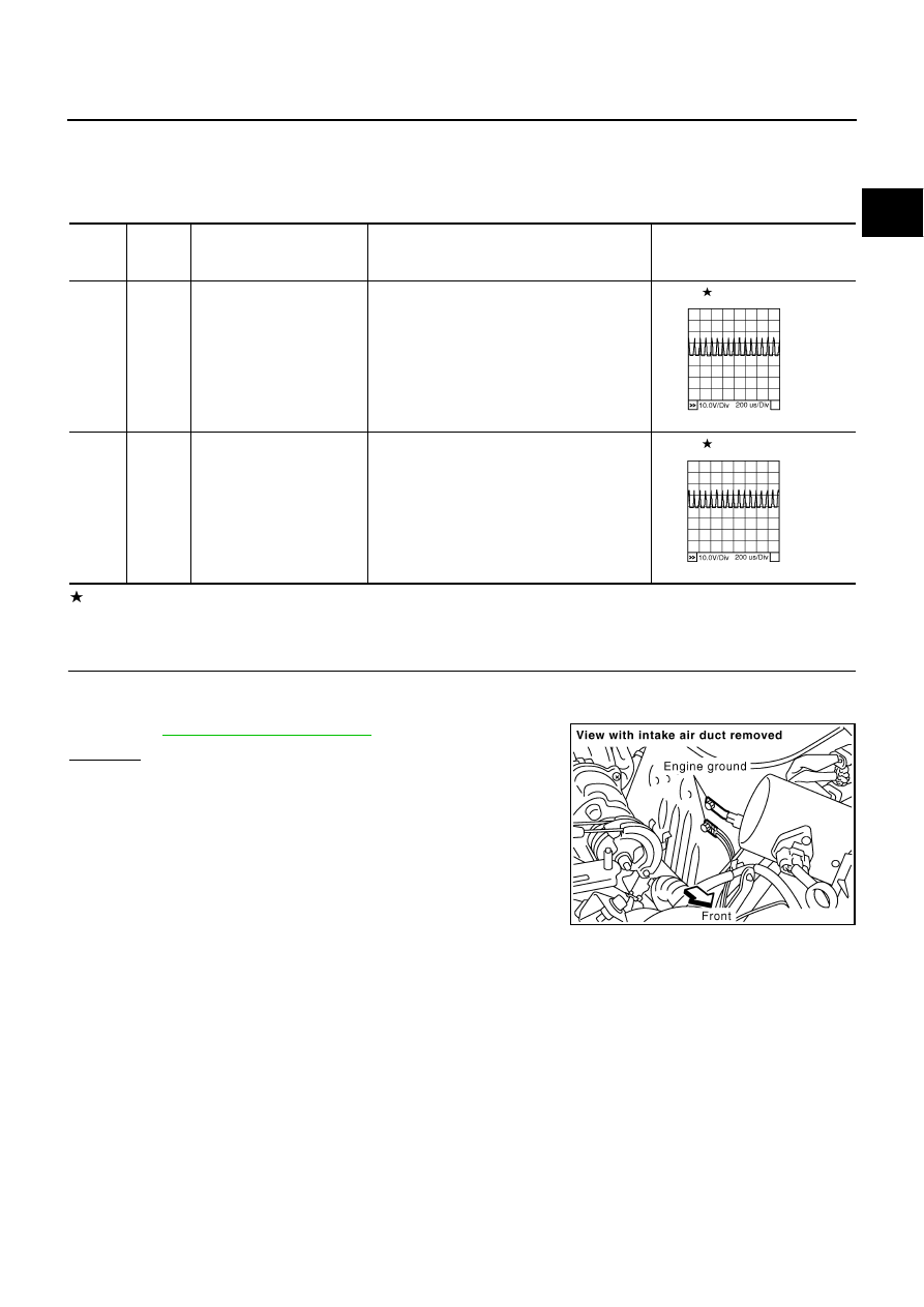
Specification data are reference values and are measured between each terminal and ground.
Pulse signal is measured by CONSULT-II.

CAUTION:

Do not use ECM ground terminals when measuring input/output voltage. Doing so may result in dam-
age to the ECM's transistor. Use a ground other than ECM terminals, such as the ground.

: Average voltage for pulse signal (Actual pulse signal can be confirmed by oscilloscope.)

Diagnostic Procedure

ABS002NX

1. 

CHECK GROUND CONNECTIONS

1.

Turn ignition switch OFF.

2.

Loosen and retighten two ground screws. 
Refer to 

EC-141, "Ground Inspection"

 .

OK or NG

OK

>> GO TO 2.

NG

>> Repair or replace ground connections.

TER-

MINAL 

NO.

WIRE 

COLOR

ITEM

CONDITION

DATA (DC Voltage)

151

L/B

Throttle control motor 
(Open)

[Ignition switch: ON]

Engine stopped

Selector lever: D

Accelerator pedal: Fully depressed

0 - 14V

154

L/W

Throttle control motor 
(Close)

[Ignition switch: ON]

Engine stopped

Selector lever: D

Accelerator pedal: Fully released

0 - 14V

PBIB0058E

PBIB0061E

PBIB1118E

EC-458

DTC P1128 THROTTLE CONTROL MOTOR

2. 

CHECK THROTTLE CONTROL MOTOR OUTPUT SIGNAL CIRCUIT FOR OPEN OR SHORT

1.

Disconnect electric throttle control actuator harness connector.

2.

Disconnect ECM harness connector.

3.

Check harness continuity between the following terminals.
Refer to Wiring Diagram.

4.

Also check harness for short to ground and short to power.

OK or NG

OK

>> GO TO 3.

NG

>> Repair or replace.

3. 

CHECK THROTTLE CONTROL MOTOR

Refer to 

EC-458, "Component Inspection"

 .

OK or NG

OK

>> GO TO 4.

NG

>> GO TO 5.

4. 

CHECK INTERMITTENT INCIDENT

Refer to 

EC-132, "TROUBLE DIAGNOSIS FOR INTERMITTENT INCIDENT"

 .

OK or NG

OK

>> GO TO 5.

NG

>> Repair or replace harness or connectors.

5. 

REPLACE ELECTRIC THROTTLE CONTROL ACTUATOR

1.

Replace the electric throttle control actuator.

2.

Perform 

EC-44, "Accelerator Pedal Released Position Learning"

 .

3.

Perform 

EC-44, "Throttle Valve Closed Position Learning"

 .

4.

Perform 

EC-44, "Idle Air Volume Learning"

 .

>> INSPECTION END

Component Inspection

ABS002NY

THROTTLE CONTROL MOTOR

1.

Disconnect electric throttle control actuator harness connector.

2.

Check resistance between terminals 3 and 6.

3.

If NG, replace electric throttle control actuator and go to next
step.

4.

Perform 

EC-44, "Accelerator Pedal Released Position Learning"

5.

Perform 

EC-44, "Throttle Valve Closed Position Learning"

 .

6.

Perform 

EC-44, "Idle Air Volume Learning"

 .

Electric throttle control 

actuator terminal

ECM terminal

Continuity

3

151

Should not exist

154

Should exist

6

151

Should exist

154

Should not exist

PBIB0015E

Resistance: Approximately 1 - 15 

 [at 25 

°

C (77

°

F)]

PBIB0095E

DTC P1128 THROTTLE CONTROL MOTOR

EC-459

C

D

E

F

G

H

I

J

K

L

M

A

EC

Removal and Installation

ABS002NZ

ELECTRIC THROTTLE CONTROL ACTUATOR

Refer to 

EM-18, "INTAKE MANIFOLD"

 .

EC-460

DTC P1140, P1145 IVT CONTROL POSITION SENSOR

DTC P1140, P1145 IVT CONTROL POSITION SENSOR

PFP:23731

Component Description

ABS002O0

Intake valve timing control position sensors are located in the front of
cylinder heads in both bank 1 and bank 2.
This sensor uses a Hall IC.
The cam position is determined by the intake primary cam sprocket
concave (in four places). The ECM provides feedback to the intake
valve timing control for appropriate target valve open-close timing
according to drive conditions based on detected cam position.

CONSULT-II Reference Value in Data Monitor Mode

ABS002O1

Specification data are reference values.

On Board Diagnosis Logic

ABS002O2

DTC Confirmation Procedure

ABS002O4

NOTE:
If DTC Confirmation Procedure has been previously conducted, always turn ignition switch OFF and wait at
least 10 seconds before conducting the next test.

 WITH CONSULT-II

1.

Turn ignition switch ON.

2.

Select “DATA MONITOR” mode with CONSULT-II.

3.

Start engine and wait let it idle for 10 seconds.

4.

If 1st trip DTC is detected, go to 

EC-464, "Diagnostic Procedure"

 .

 WITH GST

Follow the procedure WITH CONSULT-II above.

SEF359Z

MONITOR ITEM

CONDITION

SPECIFICATION

INT/V TIM (B1)
INT/V TIM (B2)

Engine: After warming up

Selector lever: P or N

Air conditioner switch: OFF

No load

Idle

5 - 5

°

CA

2,000 rpm

Approx. 0 - 20

°

CA

DTC No.

Trouble diagnosis name

DTC detecting condition

Possible cause

P1140
1140
(bank 1)

Intake valve timing control 
position sensor circuit

An excessively high or low voltage from the 
sensor is sent to ECM.

Harness or connectors
(Intake valve timing control position 
sensor circuit is open or shorted)

Intake valve timing control position 
sensor

Crankshaft position sensor (POS)

Camshaft position sensor (PHASE)

Accumulation of debris to the signal 
pick-up portion of the camshaft

P1145
1145
(bank 2)


Content   ..  440  441  442  443   ..