Infiniti M45 (Y34). Manual - part 419
DTC P0453 EVAP CONTROL SYSTEM PRESSURE SENSOR
EC-365
C
D
E
F
G
H
I
J
K
L
M
A
EC
Specification data are reference values and are measured between each terminal and ground.
CAUTION:
Do not use ECM ground terminals when measuring input/output voltage. Doing so may result in dam-
age to the ECM's transistor. Use a ground other than ECM terminals, such as the ground.
Diagnostic Procedure
ABS002L0
1.
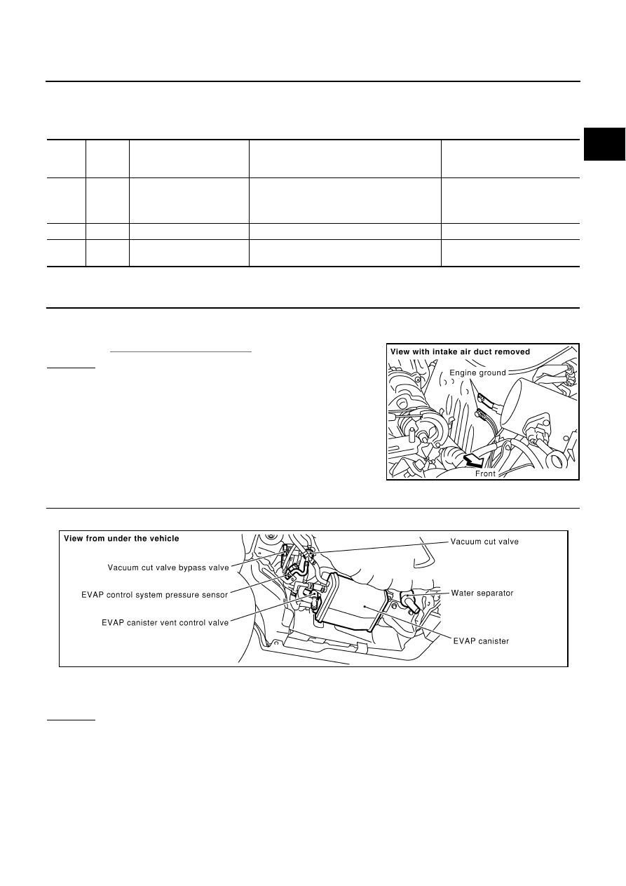
CHECK GROUND CONNECTIONS
1.
Turn ignition switch OFF.
2.
Loosen and retighten two ground screws.
Refer to
OK or NG
OK
>> GO TO 2.
NG
>> Repair or replace ground connections.
2.
CHECK CONNECTOR
1.
Disconnect EVAP control system pressure sensor harness connector.
2.
Check sensor harness connector for water.
OK or NG
OK
>> GO TO 3.
NG
>> Repair or replace harness connector.
TER-
MINAL
NO.
WIRE
COLOR
ITEM
CONDITION
DATA (DC Voltage)
89
B
Sensor ground
[Engine is running]
●
Warm-up condition
●
Idle speed
Approximately 0V
103
L
Sensor power supply
[Ignition switch: ON]
Approximately 5V
110
G
EVAP control system pres-
sure sensor
[Ignition switch: ON]
Approximately 1.8 - 4.8V
PBIB1118E
Water should not exist.
PBIB0026E