Infiniti M45 (Y34). Manual - part 418
DTC P0452 EVAP CONTROL SYSTEM PRESSURE SENSOR
EC-361
C
D
E
F
G
H
I
J
K
L
M
A
EC
12.
CHECK INTERMITTENT INCIDENT
Refer to
EC-132, "TROUBLE DIAGNOSIS FOR INTERMITTENT INCIDENT"
>> INSPECTION END
Component Inspection
ABS002KU
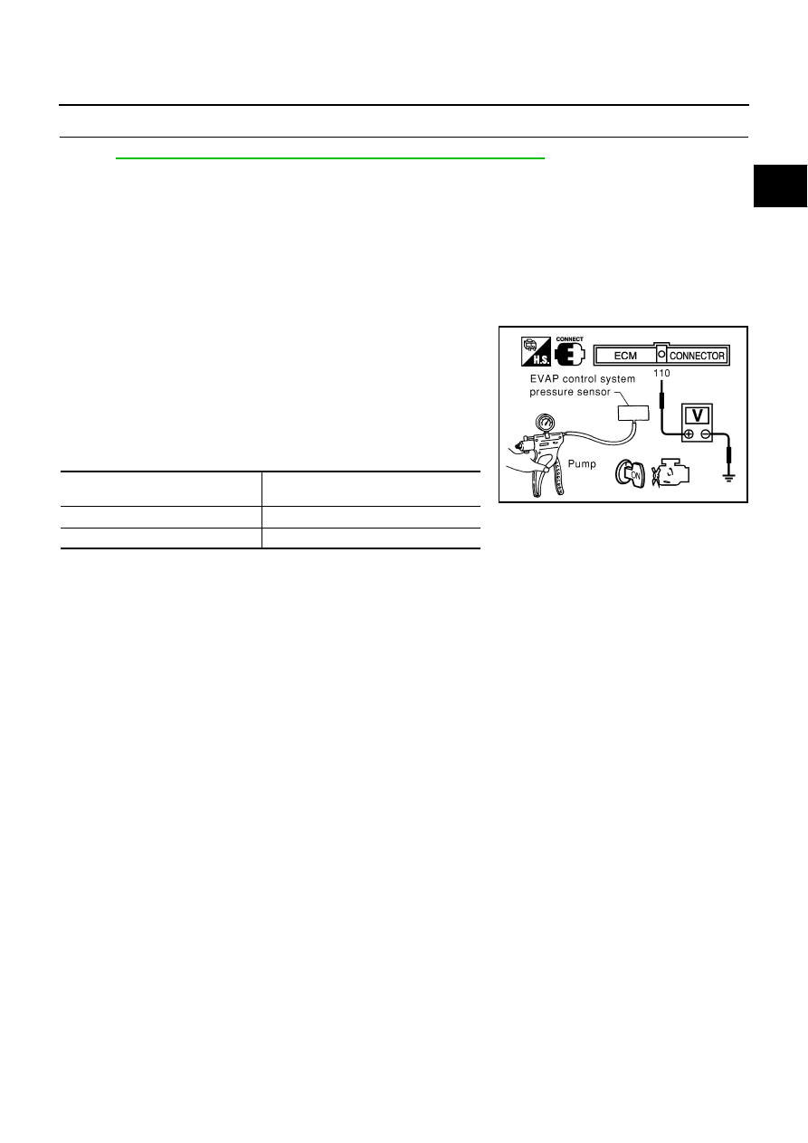
EVAP CONTROL SYSTEM PRESSURE SENSOR
1.
Remove EVAP control system pressure sensor with its harness connector connected.
2.
Remove hose from EVAP control system pressure sensor.
3.
Install a vacuum pump to EVAP control system pressure sensor.
4.
Turn ignition switch ON.
5.
Use pump to apply vacuum and pressure to EVAP control sys-
tem pressure sensor as shown in figure.
CAUTION:
●
Always calibrate the vacuum pump gauge when using it.
●
Do not apply below -93.3 kPa (-700 mmHg, -27.56 inHg) or
pressure over 101.3 kPa (760 mmHg, 29.92 inHg).
6.
Check voltage between ECM terminal 110 and ground with
CONSULT-II or tester.
CAUTION:
Discard any EVAP control system pressure sensor which has dropped from a height of more than
0.5 m (19.7 in) onto a hard surface such a concrete floor; use a new one.
7.
If NG, replace EVAP control system pressure sensor.
Applied vacuum kPa
(mmHg, inHg)
Voltage V
Not applied
1.8 - 4.8
-26.7 (-200 mmHg, -7.87)
2.1 to 2.5V lower than above value
PBIB0156E