Infiniti M45 (Y34). Manual - part 316
 

  Index      Infiniti     Infiniti M45 (Y34) - service repair manual 2004 year


Search            copyright infringement  


Content   ..  314  315  316  317   ..


Infiniti M45 (Y34). Manual - part 316


VEHICLE INFORMATION AND INTEGRATED SWITCH SYSTEM /WITHOUT 

NAVIGATION SYSTEM

DI-109

C

D

E

F

G

H

I

J

L

M

A

B

DI

42

BR/Y

Ground

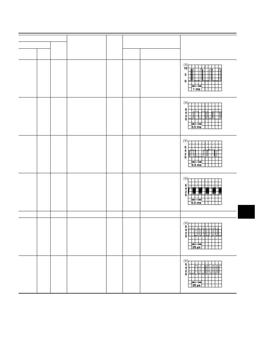
CONSULT-II commu-
nication signal (CN-
AV)

Input

ON

Perform CONSULT-II.

43

L

Ground

A/C communication 
signal (AC-AV)

Input

ON

—

44

L/W

Ground

A/C communication 
signal (AV-AC)

Output

ON

—

45

L/R

Ground

A/C clock signal

Input

ON

—

46

—

—

Shield ground

—

—

—

—

47

W/R

Ground

Communication signal 
(+)

Input/

output

ON

—

48

B/R

Ground

Communication signal 
(-)

Input/

output

ON

—

Terminals

Signal

Signal 

input/

output

Condition

Reference value

(+)

(–)

Terminal 

No.

Wire 

color

Ignition 

switch

Operation

SKIA0170E

SKIA0173E

SKIA0172E

SKIA0174E

SKIA0175E

SKIA0176E

DI-110

VEHICLE INFORMATION AND INTEGRATED SWITCH SYSTEM /WITHOUT 

NAVIGATION SYSTEM

Terminals and Reference Value for Display

AKS003ZY

Terminals

Signal

Condition

Reference value

Terminal 

No.

Wire 

color

Ignition 

switch

Operation

1

R/L

RGB signal (R: Red)

ON

Move to “Screen Adjustment” in 
the check/adjustment function.

2

R/W

RGB signal (G: Green)

ON

Move to “Screen Adjustment” in 
the check/adjustment function.

3

B

RGB signal (B: Blue)

ON

Move to “Screen Adjustment” in 
the check/adjustment function.

4

—

RGB ground

ON

—

Approx. 0V

5

W

Horizontal synchronizing sig-
nal

ON

ON screen, the volume can be 
adjusted.

6

R

Vertical synchronizing signal

ON

—

7

G

RGB synchronizing signal

ON

Press the map switch.

8

B

RGB area signal

ON

Press the vehicle information 
switch.

SKIA0165E

SKIA0166E

SKIA0167E

SKIA0163E

SKIA0161E

SKIA0164E

SKIA0162E

VEHICLE INFORMATION AND INTEGRATED SWITCH SYSTEM /WITHOUT 

NAVIGATION SYSTEM

DI-111

C

D

E

F

G

H

I

J

L

M

A

B

DI

Terminals and Reference Value for Multifunction Switch

AKS003ZZ

12

B/R

Communication signal (-)

ON

—

13

W/R

Communication signal (+)

ON

—

14

—

Shield ground

—

—

—

15

L

Communication signal (-)

ON

—

16

R

Communication signal (+)

ON

—

17

—

Shield ground

—

—

—

19

L/B

Ignition switch (ACC)

ACC

—

Battery voltage

21

SB

Battery power

OFF

—

Battery voltage

23

22

B

Ground

—

—

—

24

Terminals

Signal

Condition

Reference value

Terminal 

No.

Wire 

color

Ignition 

switch

Operation

SKIA0176E

SKIA0175E

SKIA0176E

SKIA0175E

Terminals

Signal

Condition

Reference value 

Terminal 

No.

Wire 

color

Ignition 

switch

Operation

1

L/B

Ignition switch (ACC)

ACC

—

Battery voltage

2

B

Ground

ON

—

Approx. 0V

9

R

Communication signal (+)

ON

—

SKIA0175E

DI-112

VEHICLE INFORMATION AND INTEGRATED SWITCH SYSTEM /WITHOUT 

NAVIGATION SYSTEM

On Board Self-Diagnosis Function (Without CONSULT-II)

AKS00400

DESCRIPTION 

●

Diagnosis function consists of the self-diagnosis mode performed automatically and the CONFIRMATION/
ADJUSTMENT mode operated manually.

●

Self–diagnosis mode checks for connections between the units constituting this system, analyzes each
individual unit at the same time, and displays the results on the LCD screen.

●

CONFIRMATION/ADJUSTMENT mode is used to perform trouble diagnosis that require operation and
judgment by an operator (trouble that cannot be automatically judged by the system), to check/change the
set value, and to display the History of Errors of the navigation system.

DIAGNOSIS ITEM 

10

L

Communication signal (-)

ON

—

11

—

Shield ground

—

—

—

15

Y

Communication signal (+)

ON

—

16

BR

Communication signal (-)

ON

—

17

—

Shield ground

—

—

—

Terminals

Signal

Condition

Reference value 

Terminal 

No.

Wire 

color

Ignition 

switch

Operation

SKIA0176E

SKIA0175E

SKIA0176E

Mode

Description

Self-Diagnosis

●

AV control unit diagnosis (DVD-ROM drive will not be diagnosed when no 
map DVD-ROM is in it.).

●

Analyzes connection between the AV control unit and the GPS antenna 
connection between the AV control unit and each unit, and operation of 
each unit.

CONFIRMATION/
ADJUSTMENT

Display Diagnosis

Color tone and shading of the screen can be checked by the display of a color 
bar and a gray scale.

Vehicle Signals

Analyzes the following vehicle signals: Vehicle speed signal, parking brake 
signal, light signal, ignition switch signal, and reverse signal.

Speaker Test

Checks the connection of each speaker using a test tone.

Auto Climate Control

Turns all A/C screens on display and A/C switch indicator lamp on.

Rear View Camera

Changes position of the aiming line overlapped on the rear view image.


Content   ..  314  315  316  317   ..