Infiniti M45 (Y34). Manual - part 264
 

  Index      Infiniti     Infiniti M45 (Y34) - service repair manual 2004 year


Search            copyright infringement  


Content   ..  262  263  264  265   ..


Infiniti M45 (Y34). Manual - part 264


SERVICE DATA AND SPECIFICATIONS (SDS)

BR-35

C

D

E

G

H

I

J

K

L

M

A

B

BR

SERVICE DATA AND SPECIFICATIONS (SDS)

PFP:00030

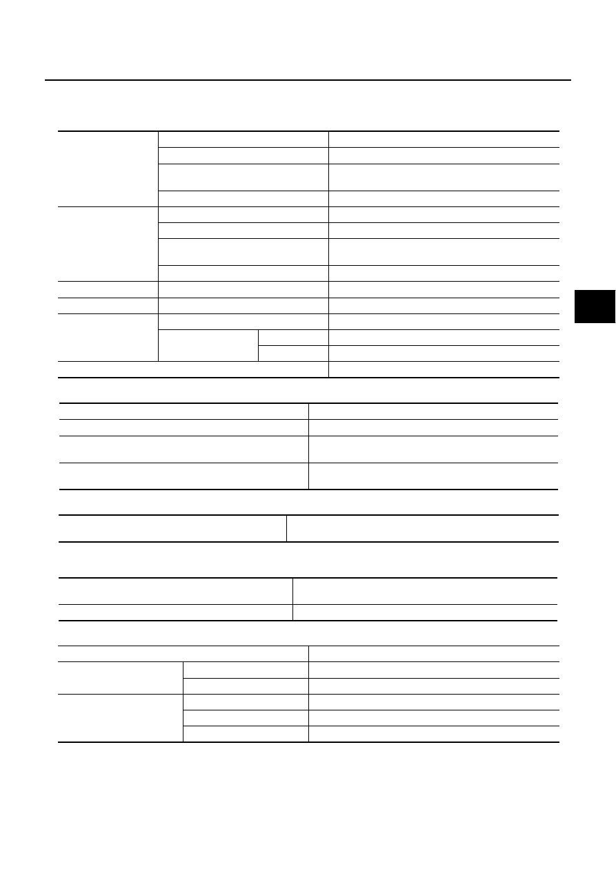
General Specifications

AFS000KP

Unit: mm (in)

Brake Pedal

AFS000KQ

Check Valve

AFS000KR

Brake Booster

AFS000KS

Vacuum Type

Front Disc Brake

AFS000KT

Front brake

Brake model

CLZ31VA

Cylinder bore diameter

45.0 (1.77) 

×

 2

Pad
Length 

×

 width 

×

 thickness

127.0 

×

 56.0 

×

 10.0 (5.00 

×

 2.20 

×

 0.394)

Rotor outer diameter 

×

 thickness

290 

×

 28 (11.42 

×

 1.10)

Rear brake 

Brake model

AD14VD

Cylinder bore diameter

43.86 (1.727)

Pad
Length 

×

 width 

×

 thickness

97.4 

×

 33.9 

×

 9.8 (3.835 

×

 1.335 

×

 0.386)

Rotor outer diameter 

×

 thickness

292 

×

 16 (11.50 

×

 0.63)

Master cylinder

Cylinder bore diameter

25.4 (1)

Control valve

Valve model

Electric brake force distribution

Brake booster

Booster model

R215T

Diaphragm diameter

Primary

230 (9.06)

Secondary

205 (8.07)

Recommended brake fluid

DOT 3

Free play (at pedal top surface)

3 - 11 mm (0.12 - 0.43 in)

Brake pedal height (from dash lower panel top surface)

174 - 184 mm (6.85 - 7.24 in)

Depressed pedal height under force of 490 N (50 kg, 110 lb)
(from dash panel top surface)

90 mm (3.54 in) or more

Clearance between the stopper rubber and the threaded end 
of the stop lamp switch/Brake switch/ASCD cancel switch

0.74 - 1.96 mm (0.0291 - 0.0772 in)

Vacuum leakage 
(at vacuum of –66.7 kPa (–500 mmHg, –19.69 inHg)

Within 1.3 kPa (10 mmHg, 0.39 inHg) of vacuum for 15 seconds

Vacuum leakage 
[at vacuum of –66.7 kPa (–500 mmHg, –19.69 inHg)]

Within 3.3 kPa (25 mmHg, 0.98 inHg) of vacuum for 15 seconds

Input rod installation standard dimension

125 mm (4.92 in)

Brake model

CLZ31VA

Brake pad

Standard thickness (new)

10 mm (0.394 in)

Repair limit thickness

2.0 mm (0.079 in)

Disc rotor

Standard thickness (new)

28.0 mm (1.102 in)

Repair limit thickness

26.0 mm (1.024 in)

Maximum runout

0.07 mm (0.0028 in) or less

BR-36

SERVICE DATA AND SPECIFICATIONS (SDS)

Rear Disc Brake

AFS000KU

Brake model

AD14VD

Brake pad

Standard thickness (new)

9.8 mm (0.386 in)

Repair limit thickness

2.0 mm (0.079 in)

Disc rotor

Standard thickness (new)

16.0 mm (0.630 in)

Repair limit thickness

14.0 mm (0.551 in)

Maximum runout

0.10 mm (0.0039 in) or less

BRC-1

BRAKE CONTROL SYSTEM

F  BRAKES

CONTENTS

C

D

E

G

H

I

J

K

L

M

SECTION 

BRC

A

B

BRC

BRAKE CONTROL SYSTEM

VDC/TCS/ABS

PRECAUTIONS .......................................................... 3

Precautions for Supplemental Restraint System 
(SRS) “AIR BAG” and “SEAT BELT PRE-TEN-
SIONER” .................................................................. 3
Precautions for Brake System .................................. 3
Precautions for Brake Control  .................................. 3

PREPARATION ........................................................... 5

Special Service Tools  ............................................... 5
Commercial Service Tools ........................................ 5

ON-VEHICLE SERVICE  ............................................. 6

Adjustment of Steering Angle Sensor Neutral Posi-
tion ........................................................................... 6

SYSTEM DESCRIPTION  ............................................ 7

System Diagram ....................................................... 7
VDC Function ........................................................... 7
TCS Function  ........................................................... 7
ABS Function  ........................................................... 8
EBD Function  ........................................................... 8
Fail-Safe Function  .................................................... 8

VDC / TCS SYSTEM ............................................. 8
ABS, EBD SYSTEM .............................................. 8

Hydraulic Circuit Diagram  ........................................ 9

CAN COMMUNICATION  .......................................... 10

System Description  ................................................ 10

TROUBLE DIAGNOSIS .............................................11

How to Proceed with Diagnosis  ..............................11

BASIC CONCEPT  ................................................11
DIAGNOSIS FLOWCHART  ................................ 12
ASKING COMPLAINTS  ...................................... 13
EXAMPLE OF DIAGNOSIS SHEET  ................... 13

Component Installation Location  ............................ 14
Schematic .............................................................. 15
Wiring Diagram — VDC — ..................................... 16
Control Unit Input/Output Signal Standard  ............. 24

REFERENCE VALUE FROM CONSULT-II  ......... 24

CONSULT-II Functions ........................................... 26

CONSULT-II MAIN FUNCTION ........................... 26
CONSULT-II BASIC OPERATION PROCEDURE 

... 26

SELF-DIAGNOSIS .............................................. 27
DATA MONITOR  ................................................. 30
ACTIVE TEST  ..................................................... 31

Correct and Quick Diagnosis .................................. 35

DIAGNOSIS PRECAUTIONS  ............................. 35

Basic Inspection  ..................................................... 37

BASIC INSPECTION 1 BRAKE FLUID AMOUNT, 
LEAKS, AND BRAKE PADS INSPECTION ......... 37
BASIC INSPECTION 2 POWER SYSTEM TER-
MINAL LOOSENESS AND BATTERY INSPEC-
TION .................................................................... 37
BASIC INSPECTION 3 ABS WARNING LAMP, 
VDC OFF LAMP, SLIP LAMP INSPECTION ....... 37

Inspection 1 Wheel Sensor System ........................ 38

INSPECTION PROCEDURE  .............................. 38

Inspection 2 Engine System  ................................... 40
Inspection 3 VDC/TCS/ABS Control Unit 1  ............ 40
Inspection 4 Pressure Sensor System  ................... 40
Inspection 5 Steering Angle Sensor System  .......... 42
Inspection 6 Yaw Rate/Side G Sensor System  ...... 43
Inspection 7 Solenoid and VDC Change-Over Valve 
System .................................................................... 45
Inspection 8 ABS Motor and Motor Relay System ... 48
Inspection 9 Solenoid Valve Relay System  ............ 50
Inspection 10 Stop Lamp Switch System  ............... 51
Inspection 11 VDC/TCS/ABS Control Unit Power 
and Ground Systems .............................................. 52
Inspection 12 VDC/TCS/ABS Control Unit 2  .......... 54
Inspection 13 Brake Fluid Level Sensor System  .... 54
Inspection 14 CAN Communication System ........... 55
Inspection 15 When “SHIFT POSITION ERROR” 
Appears in Self-Diagnosis Results Display  ............ 55
Inspecting Components .......................................... 56

VDC OFF SWITCH  ............................................. 56
VDC RELAY BOX ................................................ 56
VDC ACTUATOR  ................................................ 57

Symptom 1 Excessive ABS Function Operation Fre-
quency .................................................................... 59
Symptom 2 Unexpected Pedal Reaction ................ 60
Symptom 3 The Braking Distance Is Long  ............. 60

BRC-2

Symptom 4 The ABS Function Does Not Operate ... 60
Symptom 5 Pedal Vibration or ABS Operation 
Sound Occurs  ......................................................... 61
Symptom 6 Vehicle Jerks During VDC/TCS/ABS 
Control .................................................................... 61

WHEEL SENSORS  ................................................... 63

Removal and Installation  ........................................ 63

REMOVAL ........................................................... 63
INSTALLATION .................................................... 63

VDC/TCS/ABS CONTROL UNIT  .............................. 65

Removal and Installation  ........................................ 65

REMOVAL ........................................................... 65
INSTALLATION .................................................... 65

SENSOR ROTOR  ......................................................66

Removal and Installation .........................................66

REMOVAL ............................................................66
INSTALLATION ....................................................66

VDC/TCS/ABS ACTUATOR  ......................................67

Removal and Installation .........................................67

G SENSOR  ................................................................68

Removal and Installation .........................................68

REMOVAL ............................................................68
INSTALLATION ....................................................68

STEERING ANGLE SENSOR  ...................................69

Removal and Installation .........................................69

REMOVAL ............................................................69
INSTALLATION ....................................................69


Content   ..  262  263  264  265   ..