Infiniti M45 (Y34). Manual - part 258
BRAKE PIPING AND HOSE
BR-11
C
D
E
G
H
I
J
K
L
M
A
B
BR
BRAKE PIPING AND HOSE
PFP:46210
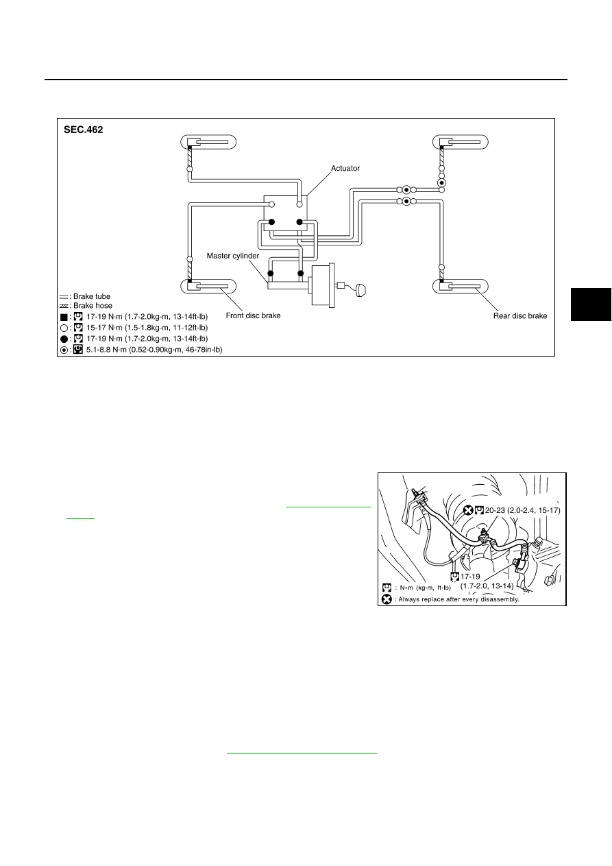
Hydraulic Circuit
AFS000K2
CAUTION:
●
When installing, check for twist and fracture.
●
Make sure that there is no interference with other parts when turning the steering clockwise or
counterclockwise.
●
The brake piping is an important safety part. If a brake fluid leak is detected, always disassemble
the parts. Replace the applicable part with a new one.
Front Brake Piping and Hose
AFS000K3
REMOVAL
1.
Connect a vinyl tube to the bleed valve.
2.
Drain brake fluid gradually from the bleed valve of each wheel
while depressing the brake pedal. Refer to
3.
Cover the brake line connection to prevent foreign material such
as dust or dirt from entering into the connection.
4.
Using a flare nut wrench, remove the brake tube from the brake
hose. Remove the union bolt, and remove the brake hose from
the caliper assembly.
5.
Remove the lock plate.
6.
Remove the mounting nuts, and remove the brake hose from
the vehicle.
INSTALLATION
1.
Install the brake hose by aligning with the protrusion on the caliper assembly, and tighten the union bolts
to the specified torque.
CAUTION:
●
Do not reuse the copper washer.
2.
Install the brake hose to the brake tube on the vehicle, and temporarily tighten the flare nut by hand until it
stops to install the bracket. Fix it with the lock plate, and tighten it to the specified torque.
3.
Install the brake hose to the vehicle, and tighten the mounting nuts to the specified torque.
4.
After the work, bleed air. Refer to
SFIA2233E
SFIA2234E