Infiniti M45 (Y34). Manual - part 257
BRAKE PEDAL
BR-7
C
D
E
G
H
I
J
K
L
M
A
B
BR
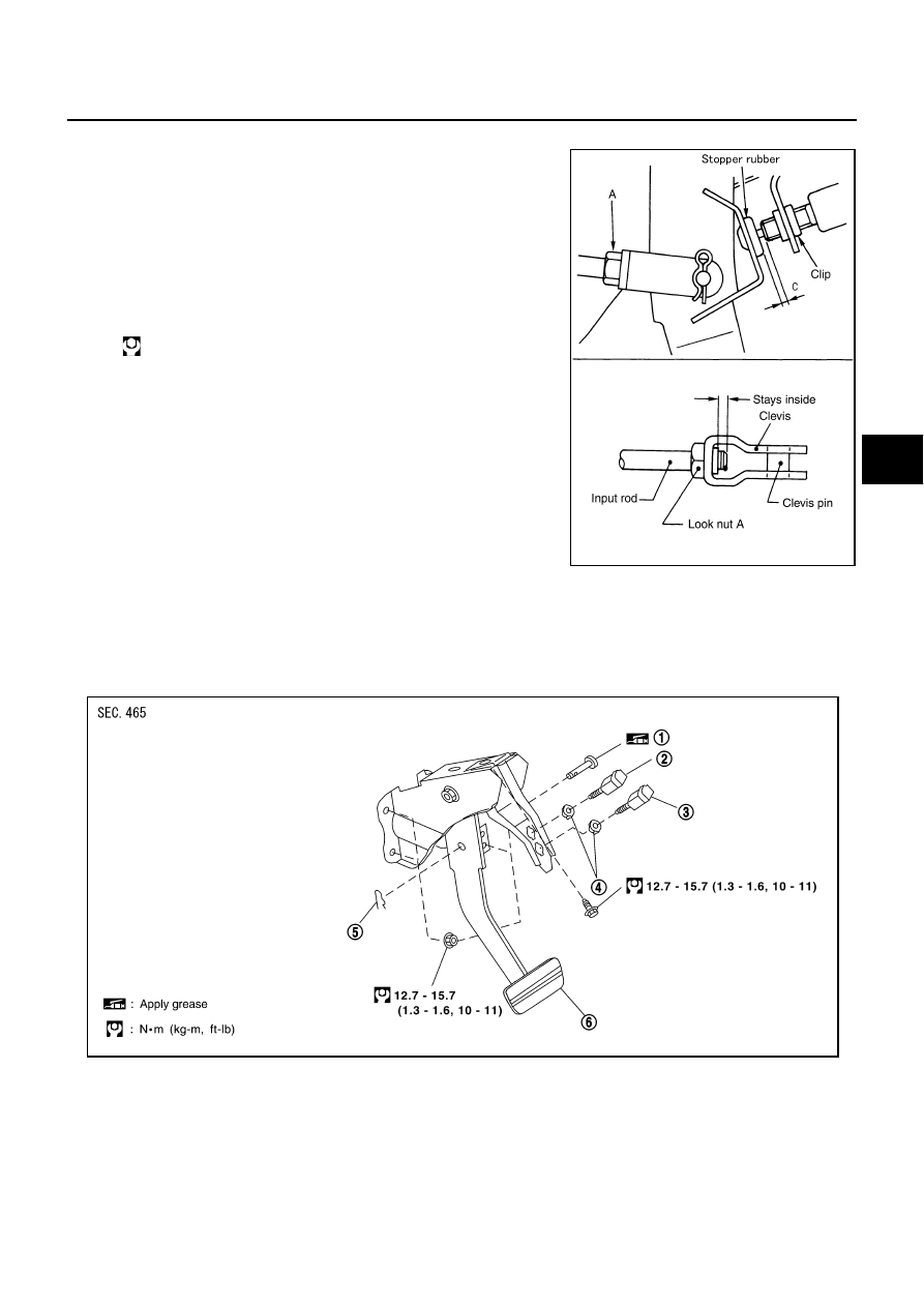
ADJUSTMENT
1.
Loosen the stop lamp switch and brake switch (or ASCD cancel
switch) by rotating it counterclockwise by 45
°
.
2.
Loosen the lock nut (A) on the input rod, then rotate the input
rod to set the pedal to the specified height, and tighten the lock
nut (A).
CAUTION:
Check that the threaded end of the input rod stays inside
the clevis.
3.
With the pedal pulled and held by hand, press the stop lamp
switch and brake switch (or ASCD cancel switch) with their
threaded end contacts the stopper rubber.
4.
With the threaded end of the stop lamp switch contacting the
stopper rubber brake switch (or ASCD cancel switch), rotate the
switch clockwise by 45
°
to secure.
CAUTION:
Make sure that the clearance (C) between the stopper rub-
ber and threaded end of the stop lamp switch and brake
switch (or ASCD cancel switch) is within the standard.
5.
Check the pedal play.
CAUTION:
Make sure that the stop lamps go off when the pedal is released.
6.
Start the engine to check the brake pedal's depressed height.
Removal and Installation
AFS000JY
COMPONENT PARTS DRAWING
Lock nut (A):
: 16 - 22 N·m (1.7 - 2.1 kg-m, 12 - 15 in-lb)
SFIA0160E
1.
Clevis pin
2.
Stop lamp switch
3.
ASCD cancel switch
Brake switch (Models with ICC)
4.
Clip
5.
Snap pin
6.
Brake pedal
SFIA1923E