Infiniti M45 (Y34). Manual - part 221


  Index      Infiniti     Infiniti M45 (Y34) - service repair manual 2004 year


Search            copyright infringement  


Content   ..  219  220  221  222   ..


Infiniti M45 (Y34). Manual - part 221


FRONT DOOR LOCK

BL-109

C

D

E

F

G

H

J

K

L

M

A

B

BL

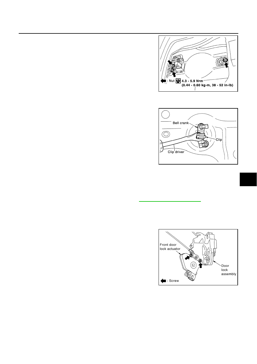
13. Remove the exterior handle mounting bolts, move the exterior

handle assembly backward, and then remove it from the panel
in front of the exterior handle escutcheon.

14. Using a screwdriver or similar tool, remove the door key cylinder status switch from the key cylinder

(driver side only).

15. Using a clip driver or similar tool, remove the bell crank's plastic

clip.

INSTALLATION

Install in the reverse order of removal.

CAUTION:

To install each rod, be sure to rotate the rod holder until a click is felt.

After installing, check operation.

After installing, perform fitting adjustment. Refer to 

BL-103, "Fitting Adjustment"

 .

Disassembly and Assembly

AIS001EF

DISASSEMBLY

CAUTION:

Be sure to remove or install the actuator with the door lock assembly removed.

1.

Remove the mounting screws, and remove the actuator from the
door lock assembly.

2.

Pull the actuator straight downward to separate it from the door
lock assembly.

ASSEMBLY

1.

Align the actuator pivot with the cutout on the knob lever of the door lock assembly, then assemble the
actuator.

2.

Move the knob lever and the actuator pivot toward the lock-on direction, and check that it engages
securely.

PIIA2779E

PIIA2780E

PIIA2781E

BL-110

REAR DOOR LOCK

REAR DOOR LOCK

PFP:82502

Components

AIS001EG

Inspection and Adjustment

AIS001EH

1.

Remove the rear door finisher. Refer to 

EI-31, "Removal and Installation"

 .

2.

Remove the sealing screen assembly.

3.

Remove the rear window. Refer to 

GW-53, "Removal and Installation"

 .

EXTERIOR HANDLE ROD ADJUSTMENT

Rotate the bushing to adjust so that the clearance between the bush-
ing and rod becomes as shown in the figure.

CAUTION:

Be careful not to make the clearance 0 mm (0 in) or the rod
pressed continuously.

Removal and Installation

AIS001Q4

REMOVAL

1.

Remove the rear door finisher. Refer to 

EI-31, "Removal and Installation"

 .

2.

Remove the sealing screen assembly

3.

Remove the rear door window. Refer to 

GW-53, "Removal and Installation"

 .

4.

Remove the inside handle escutcheon A.

5.

Remove the mounting screw, and remove the inside handle.

1.

Outside handle rod

2.

Outside handle

3.

Door lock assembly

4.

Door lock actuator

5.

Knob rod protector

6.

Inside handle rod

7.

Rod holder

8.

Lock knob rod

9.

Lock knob

10. Inside handle

11.

Inside handle escutcheon A

PIIA2782E

SBT978

REAR DOOR LOCK

BL-111

C

D

E

F

G

H

J

K

L

M

A

B

BL

6.

Using a screwdriver or similar tool, open the rod holder and
remove the rod.

7.

Remove the mounting screws and nut, remove the knob rod protector.

8.

Disconnect inside handle rod door lock assembly side.

9.

Slide inside handle rearward and remove it.

10. Disconnect the door lock actuator connector.

11. Remove the mounting bolts (TORX T30), remove the door lock

assembly.

12. Remove the exterior handle mounting bolts, move the exterior

handle assembly backward, and then remove it from the panel
in front of the exterior handle escutcheon.

INSTALLATION

Install in the reverse order of removal.

CAUTION:

To install each rod, be sure to rotate the rod holder until a click is felt.

After installing, check operation.

After installing, perform fitting adjustment. Refer to 

BL-103, "Fitting Adjustment"

 .

PIIA2784E

PIIA2783E

PIIA1090E

PIIA2779E

BL-112

REAR DOOR LOCK

Disassembly and Assembly

AIS001EJ

DISASSEMBLY

CAUTION:

Be sure to remove or install the actuator with the door lock assembly removed.

1.

Remove the mounting screws, and remove the actuator from the
door lock assembly.

2.

Pull the actuator straight downward to separate it from the door
lock assembly.

ASSEMBLY

1.

Align the actuator pivot with the cutout on the knob lever of the door lock assembly, then assemble the
actuator.

2.

Move the knob lever and the actuator pivot toward the lock-on direction, and check that it engages
securely.

PIIA2786E


Content   ..  219  220  221  222   ..