Infiniti M45 (Y34). Manual - part 89


  Index      Infiniti     Infiniti M45 (Y34) - service repair manual 2004 year


Search            copyright infringement  


Content   ..  87  88  89  90   ..


Infiniti M45 (Y34). Manual - part 89


DTC P1843 ATF PRESSURE SWITCH 3

AT-241

D

E

F

G

H

I

J

K

L

M

A

B

AT

3. 

CHECK TERMINAL CORD ASSEMBLY

1.

Remove oil pan. Refer to 

AT-312, "Control Valve Assembly"

 .

2.

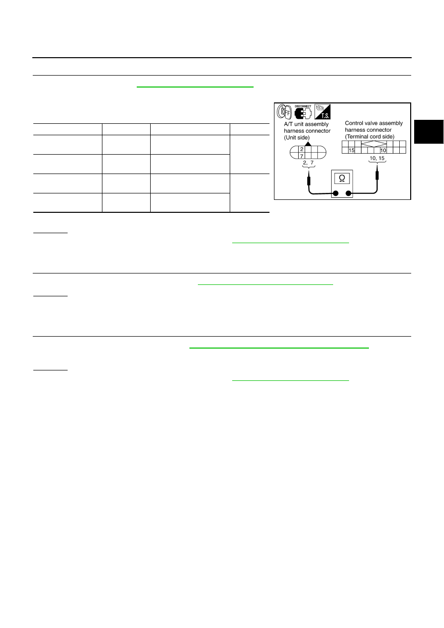
Disconnect A/T unit assembly harness connector and control valve assembly harness connector.

3.

Check continuity between A/T unit assembly harness connector
and control valve assembly harness connector.

4.

If OK, check harness for short to ground and short to power.

OK or NG

OK

>> Replace the control valve assembly. Refer to 

AT-312, "Control Valve Assembly"

 .

NG

>> Repair open circuit or short to ground or short to power in harness or connectors.

4. 

CHECK DTC

Perform DTC confirmation procedure. Refer to  

AT-238, "DTC Confirmation Procedure"

 .

OK or NG

OK

>> INSPECTION END

NG

>> GO TO 5.

5. 

CHECK TCM

1.

Check TCM input/output signal. Refer to 

AT-86, "TCM Input/Output Signal Reference Values"

 .

2.

If NG, recheck TCM pin terminals for damage or loose connection with harness connector.

OK or NG

OK

>> Replace the control valve assembly. Refer to 

AT-312, "Control Valve Assembly"

 .

NG

>> Repair or replace damaged parts.

Item

Connector No.

Terminal No. (Wire color)

Continuity

A/T unit assembly 
harness connector

F26

2 (R)

Yes

Control valve assem-
bly harness connector

F302

10 (R)

A/T unit assembly 
harness connector

F26

7 (W)

Yes

Control valve assem-
bly harness connector

F302

15 (W)

SCIA3100E

AT-242

DTC P1845 ATF PRESSURE SWITCH 5

DTC P1845 ATF PRESSURE SWITCH 5

PFP:25240

Description

ACS004B4

Fail-safe function to detect direct clutch solenoid valve condition.

CONSULT-II Reference Value

ACS004PT

On Board Diagnosis Logic

ACS004B5

This is not an OBD-II self-diagnostic item.

Diagnostic trouble code “ATF PRES SW 5/CIRC” with CONSULT-II is detected, when TCM detects that
actual gear ratio is normal, and relation between gear position and condition of ATF pressure switch 5 is
irregular during depressing accelerator pedal. (Other than during shift change)

Possible Cause

ACS004B6

ATF pressure switch 5

Harness or connectors
(The switch circuit is open or shorted.)

DTC Confirmation Procedure

ACS004B7

CAUTION:

Always drive vehicle at a safe speed.

NOTE:
If “DTC Confirmation Procedure” has been previously conducted, always turn ignition switch OFF and
wait at least 10 seconds before conducting the next test.
After the repair, perform the following procedure to confirm the malfunction is eliminated.

 WITH CONSULT-II

1.

Start engine.

2.

Accelerate vehicle to maintain the following condition.
ACCELE POS: 1.5/8 - 2.0/8
Selector lever: “D” position 
Gear position: 1st 

Þ

 2nd Gear (D/C ON/OFF) 

3.

Perform step “2” again.

4.

Turn ignition switch OFF, then perform step “1” to “3” again.

5.

Check “SELF-DIAG RESULTS” mode for “A/T” with CONSULT-
II.
If DTC (P1845) is detected, go to 

AT-244, "Diagnostic Proce-

dure"

 .

If DTC (P1762) is detected, go to 

AT-201, "Diagnostic Procedure"

 .

Item name

Condition 

Display value

ATF PRES SW 5

Direct clutch solenoid valve operates. 

OFF

Other conditions

ON

SAT014K

DTC P1845 ATF PRESSURE SWITCH 5

AT-243

D

E

F

G

H

I

J

K

L

M

A

B

AT

Wiring Diagram — AT — FPSW5

ACS004B8

TCWA0138E

AT-244

DTC P1845 ATF PRESSURE SWITCH 5

TCM terminals and data are reference value.

Diagnostic Procedure

ACS004B9

1. 

CHECK INPUT SIGNALS

 With CONSULT-II

1.

Start engine.

2.

Select “ECU INPUT SIGNALS” or “MAIN SIGNALS” in “DATA
MONITOR” mode for “A/T” with CONSULT-II.

3.

Accelerate vehicle in “D” position (1st 

Þ

 2nd gear), and confirm

the ON/OFF actuation of the “ATF PRES SW 5”.

OK or NG

OK

>> GO TO 4.

NG

>> GO TO 2.

2. 

CHECK HARNESS BETWEEN TCM AND A/T UNIT ASSEMBLY HARNESS CONNECTOR

1.

Turn ignition switch OFF.

2.

Disconnect TCM connector.

3.

Check continuity between A/T unit assembly harness connector
and TCM connector.

4.

If OK, check harness for short to ground and short to power.

5.

Reinstall any part removed.

OK or NG

OK

>> GO TO 3.

NG

>> Repair open circuit or short to ground or short to power in harness or connectors.

Terminal   

No.

Wire 

color

Item

Condition

Data (Approx.)

22

P/B

SEL2 (ATF pres-
sure switch 5)

40

Y/G

DATA BIT1

Item name

Condition 

Display value

ATF PRES SW 5

Direct clutch solenoid 
valve operates. 

OFF

Other conditions

ON

PCIA0067E

Item

Connector No.

Terminal No. 

(Wire color)

Continuity

TCM

F103

22 (P/B)

Yes

A/T unit assembly harness 
connector

F26

6 (P/B)

TCM

F104

40 (Y/G)

Yes

A/T unit assembly harness 
connector

F26

2 (Y/G)

SCIA3101E


Content   ..  87  88  89  90   ..