Infiniti M45 (Y34). Manual - part 87


  Index      Infiniti     Infiniti M45 (Y34) - service repair manual 2004 year


Search            copyright infringement  


Content   ..  85  86  87  88   ..


Infiniti M45 (Y34). Manual - part 87


DTC P1815 MANUAL MODE SWITCH

AT-233

D

E

F

G

H

I

J

K

L

M

A

B

AT

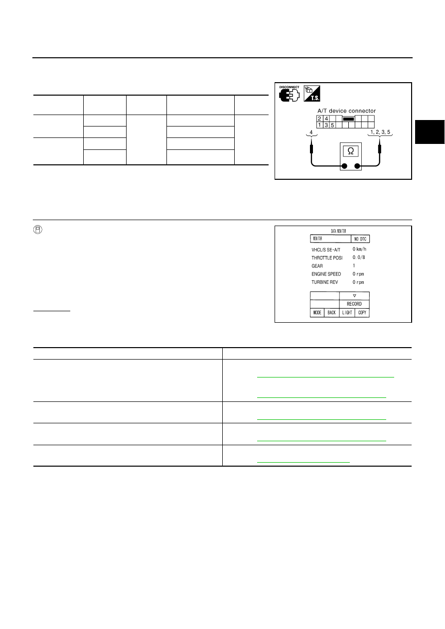
Component Inspection

ACS004AQ

MANUAL MODE SWITCH

Check continuity between terminals.

A/T Position Indicator

ACS004AR

DIAGNOSTIC PROCEDURE

1. 

CHECK INPUT SIGNALS

 With CONSULT-II

1.

Start engine.

2.

Select “MAIN SIGNALS” in “DATA MONITOR” mode for A/T with
CONSULT-II and read out the value of “GEAR”.

3.

Drive vehicle in the manual mode, and confirm that the actual
gear position and the meter's indication of the position mutually
coincide when the select lever is shifted to the “+ (up)” or “-
(down)” side (1st 

 5th gear).

 OK or NG

OK

>> INSPECTION END

NG

>> Check the following items.

A/T Position Indicator Symptom Chart

Item

Position

Connector 

No.

Terminal No.

(Unit side)

Continuity

Manual mode 
select switch

Auto

M97

4 - 5

Yes

Manual

1 - 4

Manual mode 
position select 
switch

Up

3 - 4

Down

2 - 4

SCIA4626E

PCIA0065E

Items

Presumed location of trouble

The actual gear position does not change, or shifting into the 
manual mode is not possible (no gear shifting in the manual mode 
possible).
The A/T position indicator is not indicated.

Manual mode switch 

Refer to 

AT-230, "DTC P1815 MANUAL MODE SWITCH"

 .

A/T main system (Fail-safe function actuated)

Refer to 

AT-92, "SELF-DIAGNOSTIC RESULT MODE"

 .

The actual gear position changes, but the A/T position indicator is 
not indicated.

Execute the self-diagnosis function.

Refer to 

AT-92, "SELF-DIAGNOSTIC RESULT MODE"

 .

The actual gear position and the indication on the A/T position 
indicator do not coincide.

Execute the self-diagnosis function.

Refer to 

AT-92, "SELF-DIAGNOSTIC RESULT MODE"

 .

Only a specific position or positions is/are not indicated on the A/T 
position indicator.

Check the combination meter.

Refer to 

DI-6, "COMBINATION METERS"

 .

AT-234

DTC P1841 ATF PRESSURE SWITCH 1

DTC P1841 ATF PRESSURE SWITCH 1

PFP:25240

Description

ACS004AS

Fail-safe function to detect front brake clutch solenoid valve condition.

CONSULT-II Reference Value

ACS004PR

On Board Diagnosis Logic

ACS004AT

This is not an OBD-II self-diagnostic item.

Diagnostic trouble code “ATF PRES SW 1/CIRC” with CONSULT-II is detected, when TCM detects that
actual gear ratio is normal, and relation between gear position and condition of ATF pressure switch 1 is
irregular during depressing accelerator pedal. (Other than during shift change)

Possible Cause

ACS004AU

ATF pressure switch 1

Harness or connectors
(The switch circuit is open or shorted.)

DTC Confirmation Procedure

ACS004AV

CAUTION:

Always drive vehicle at a safe speed.

NOTE:
If “DTC Confirmation Procedure” has been previously conducted, always turn ignition switch OFF and
wait at least 10 seconds before conducting the next test.
After the repair, perform the following procedure to confirm the malfunction is eliminated.

 WITH CONSULT-II

1.

Start engine.

2.

Accelerate vehicle to maintain the following condition.
ACCELE POS: 1.5/8 - 2.0/8
Selector lever: “D” position 
Gear position: 3rd 

Þ

 4th Gear   (FR/B ON/OFF) 

3.

Perform step “2” again.

4.

Turn ignition switch OFF, then perform step “1” to “3” again.

5.

Check “SELF-DIAG RESULTS” mode for “A/T” with CONSULT-
II.
If DTC (P1841) is detected, go to 

AT-236, "Diagnostic Proce-

dure"

 .

If DTC (P1757) is detected, go to 

AT-191, "Diagnostic Procedure"

 .

Item name

Condition 

Display value

ATF PRES SW 1

Front brake solenoid valve operates. 

ON

Other conditions

OFF

SAT014K

DTC P1841 ATF PRESSURE SWITCH 1

AT-235

D

E

F

G

H

I

J

K

L

M

A

B

AT

Wiring Diagram — AT — FPSW1

ACS004AW

TCWA0136E

AT-236

DTC P1841 ATF PRESSURE SWITCH 1

TCM terminal and data are reference value. Measured between each terminal and ground.

Diagnostic Procedure

ACS004AX

1. 

CHECK INPUT SIGNALS

 With CONSULT-II

1.

Start engine.

2.

Select “ECU INPUT SIGNALS” or “MAIN SIGNALS” in “DATA
MONITOR” mode for “A/T” with CONSULT-II.

3.

Accelerate vehicle in “D” position (3rd 

Þ

 4th gear), and confirm

the ON/OFF actuation of the “ATF PRES SW 1”.

 Without CONSULT-II

1.

Start engine.

2.

Accelerate vehicle in “D” position (3rd 

Þ

 4th gear).

OK or NG

OK

>> GO TO 4.

NG

>> GO TO 2.

2. 

CHECK POWER SOURCE CIRCUIT

1.

Turn ignition switch OFF.

2.

Disconnect TCM connector.

3.

Check continuity between A/T unit assembly harness connector
and TCM connector.

4.

If OK, check harness for short to ground and short to power.

5.

Reinstall any part removed.

OK or NG

OK

>> GO TO 3.

NG

>> Repair open circuit or short to ground or short to power in harness or connectors.

Terminal   

No.

Wire 

color

Item

Condition

Data (Approx.)

35

B/Y

PSB2 (ATF pres-
sure switch 1)

When 

vehicle 

starts

When front brake solenoid valve OFF.

Battery voltage

When front brake solenoid valve ON.

0V

Item name

Condition 

Display value

ATF PRES SW 1

Front brake solenoid 
valve operates. 

ON

Other conditions

OFF

PCIA0067E

Solenoid valve

Connector 

No.

Terminal No. 

(Wire color)

Voltage

Front brake solenoid 
valve

OFF

F104

35 (B/Y) - Ground

Battery voltage

ON

Approx. 0 V

PCIA0066E

Item

Connector No.

Terminal No. 

(Wire color)

Continuity

TCM

F104

35 (B/Y)

Yes

A/T unit assembly harness 
connector

F26

3 (B/Y)

SCIA3097E


Content   ..  85  86  87  88   ..