Index Infiniti Infiniti F50 - service repair manual 2006 year
Search
Content .. 828 829 830 831 ..
Infiniti F50. Manual - part 830
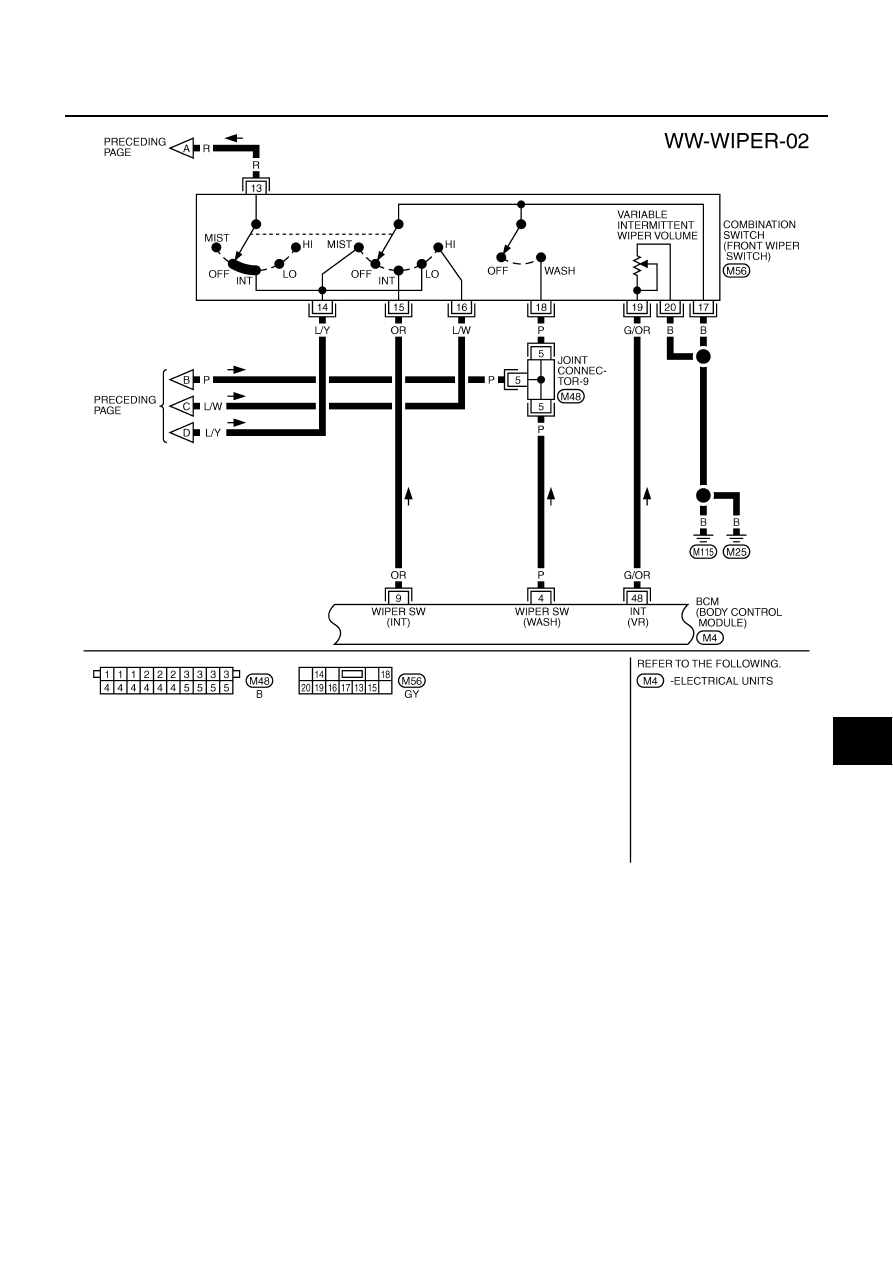
WASHER SYSTEM
WW-7
C
D
E
F
G
H
I
J
L
M
A
B
WW
TKWM0431E