Infiniti F50. Manual - part 735
REAR LOWER LINK & COIL SPRING
RSU-15
C
D
F
G
H
I
J
K
L
M
A
B
RSU
REAR LOWER LINK & COIL SPRING
PFP:551B0
Removal and Installation
EES000UI
REMOVAL
1.
Remove tire with power tool.
2.
Set jack under rear lower link.
3.
Loosen fixing bolt and nut of rear lower link in side of rear suspension member, and then remove fixing
bolt and nut in side of axle.
4.
Slowly lower jack, then remove upper seat, coil spring and rubber seat from rear lower link.
5.
Remove fixing bolt and nut in side of rear suspension member to remove rear lower link.
INSPECTION AFTER REMOVAL
●
Check rear lower link, bushing and coil spring for deformation, cracks, and damage. Replace rear lower
link and coil spring if necessary.
INSTALLATION
●
Refer to
for tightening torque. Tighten in the reverse order of removal.
CAUTION:
Refer to component parts location and do not reuse non-reusable parts.
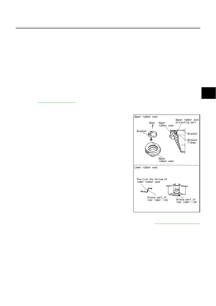
●
Check that the projecting part inside upper seat and the flange
part of bracket are attached as shown in the figure.
●
Check that the projection part outside upper seat directs to vehi-
cle front.
●
Position the hollow of rubber seat with the groove part of rear
lower link to install.
●
Install coil spring with the side of 2 paint markers directing to
lower side.
●
Perform final tightening of rear suspension member and axle installation position (rubber bushing) under
unladen condition with tires on level ground. Check wheel alignment. Refer to
.
SEIA0077E