Infiniti F50. Manual - part 734
SUSPENSION ARM
RSU-11
C
D
F
G
H
I
J
K
L
M
A
B
RSU
SUSPENSION ARM
PFP:55501
Removal and Installation
EES000UF
REMOVAL
1.
Remove tire with power tool.
2.
Remove brake caliper with power tool. Hang it in a place where it will not interfere with work. Refer to
CAUTION:
Avoid depressing brake pedal while brake caliper is removed.
3.
Remove stabilizer connecting rod mounting bracket from suspension arm with power tool.
4.
Remove fixing bolts and nuts in suspension member side of suspension arm with power tool.
5.
Remove cotter pin of suspension arm ball joint, then loosen mounting nut.
6.
Use a ball joint remover (suitable tool) to remove suspension arm from axle. Be careful not to damage ball
joint boot.
CAUTION:
To prevent damage to threads and to prevent ball joint remover (suitable tool) from coming off,
and temporarily tighten lock nuts.
INSPECTION AFTER REMOVAL
Visual Inspection
●
Check suspension arm and bushing for deformation, cracks, or damage. If any non-standard condition is
found, replace it.
●
Check boot of ball joint for cracks, or damage, and also for grease leakage.
Ball Joint Inspection
●
Manually move ball stud to confirm it moves smoothly with no binding.
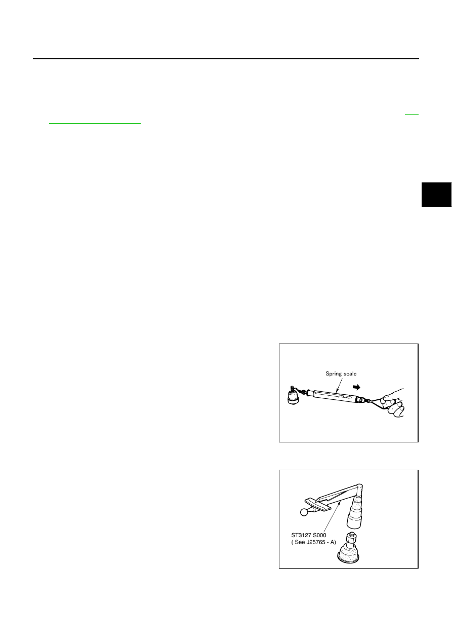
Swing Torque Inspection
CAUTION:
Before measuring, move ball joint at least ten times by hand to check for smooth movement.
●
Hook spring scale at cotter pin mounting hole. Confirm spring
scale measurement value is within specifications when ball stud
begins moving.
●
If it is outside the specified range, replace suspension arm
assembly.
Rotating Torque Inspection
●
Attach mounting nut to ball stud. Check that rotating torque is
within specifications with a preload gauge (special service tool).
●
If it is outside the specified range, replace suspension arm
assembly.
Standard value
Swing torque:
0.50 - 3.43 N·m (0.05 - 0.35 kg-m, 5 - 30 in-lb)
Measured value of spring scale:
7.85 - 54.4 N (0.80 - 5.55 kg, 1.77 - 12.27 lb)
SDIA1143E
Standard value
Rotating torque:
0.50 - 3.43 N·m (0.05 - 0.35 kg-m, 5 - 30 in-lb)
SDIA1150E