Infiniti F50. Manual - part 295
COMBINATION METERS
DI-23
C
D
E
F
G
H
I
J
L
M
A
B
DI
Inspection/Water Temperature Gauge
EKS00105
1.
CHECK ECM SYSTEM
Preform the ECM self-diagnosis. Refer to
EC-52, "Emission-related Diagnostic Information"
OK or NG
OK
>> Replace unified meter control unit (sub).
NG
>> Perform “Diagnostic Procedure” for displayed DTC.
Inspection/Vehicle Speed Signal
EKS00106
1.
CHECK VDC/TCS/ABS CONTROL UNIT SYSTEM
Preform VDC/TCS/ABS control unit self-diagnosis. Refer to
BRC-26, "CONSULT-II Functions"
OK or NG
OK
>> Replace unified meter control unit (sub).
NG
>> Check VDC/TCS/ABS control unit.
Inspection/Fuel Level Sensor Unit
EKS00107
FUEL LEVEL SENSOR UNIT
The following symptoms do not indicate a malfunction.
●
Depending on vehicle posture or driving circumstance, the fuel level in the tank various, and the pointer
may fluctuate.
●
If the vehicle is fueled with the ignition switch ON, the pointer will move slowly.
LOW-FUEL WARNING LAMP
Depending on vehicle posture or driving circumstance, the fuel level in the tank varies, and the warning lamp
ON timing may be changed.
1.
CHECK HARNESS CONNECTOR
1.
Turn the ignition switch OFF.
2.
Check combination meter, fuel level sensor unit and terminals (meter-side, and harness-side) for poor
connection and bend.
OK or NG
OK
>> GO TO 2.
NG
>> Repair terminals or connectors.
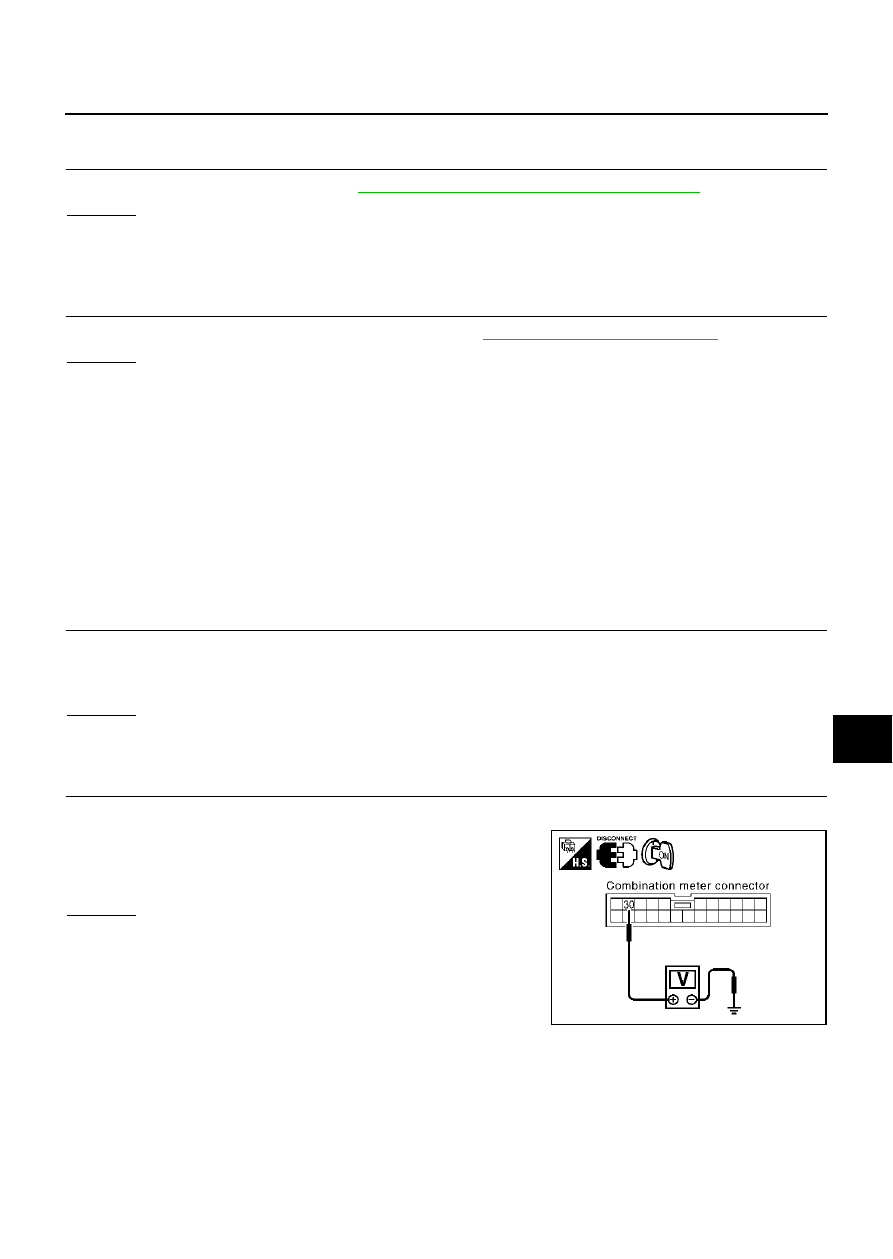
2.
CHECK HARNESS CONNECTOR OUTPUT SIGNAL
1.
Turn the ignition switch ON.
2.
Check voltage between combination meter harness connector
M42 terminal 30 (R/L) and ground.
OK or NG
OK
>> GO TO 3.
NG
>> Replace unified meter control unit (sub).
Approx. 5V
SKIA4128E