Infiniti F50. Manual - part 294
COMBINATION METERS
DI-19
C
D
E
F
G
H
I
J
L
M
A
B
DI
Work Flow
EKS001C6
1.
CHECK WARNING LAMPS
1.
Turn ignition switch ON.
2.
Warning lamps should illuminate (seat belt warning or door warning etc.).
Do warning lamps illuminate?
YES
>> GO TO 2.
NO
>> Power supply and ground check. Refer to
DI-21, "Power Supply and Ground Circuit Check"
2.
CHECK INDICATOR LAMPS
Meter/gauges/A/T indicator should indicate.
Do indicators indicate?
YES
>> GO TO 3.
NO
>> Fluorescent lamp check. Refer to
DI-22, "Fluorescent Lamp Check"
3.
CHECK SELF-DIAGNOSIS MODE OPERATION
Preform self-diagnosis mode. Refer to
DI-18, "Meter/Gauges Operation, Odo/Trip Meter, A/T Indicator and
Can diagnosis mode be activated?
YES
>> GO TO 4.
NO
>> Replace unified meter control unit (sub).
4.
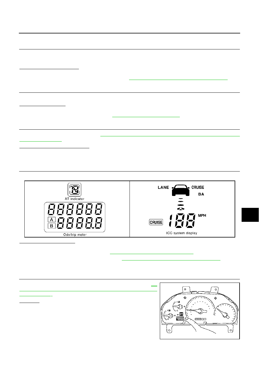
CHECK SEGMENTS
Check odo/trip meter segment, A/T indicator or ICC system display segment.
Do all segments illuminate?
YES
>> GO TO 5.
NO
>>
●
Check A/T indicator. Refer to
DI-55, "A/T Indicator Does Not Illuminate"
●
Check ICC system display. Refer to
DI-26, "ICC System Display Does Not Illuminate"
.
●
Replace unified meter control unit (sub) and meter and gauge assembly.
5.
CHECK SELF-DIAGNOSIS MODE
Check meter/gauge operation in self-diagnosis mode. Refer to
18, "Meter/Gauges Operation, Odo/Trip Meter, A/T Indicator and ICC
System Display"
OK or NG
OK
>> Symptom chart 2.
NG
>> Symptom chart 1.
SKIA3720E
SKIA0484E