Infiniti I30 (A33). Manual - part 420


  Index      Infiniti     Infiniti I30 (A33) - service repair manual 2001 year


Search            


Content   ..  418  419  420  421   ..


Infiniti I30 (A33). Manual - part 420


REMOTE CONTROLLER BATTERY AND FUNCTION
CHECK

=NHEL0195S02

1

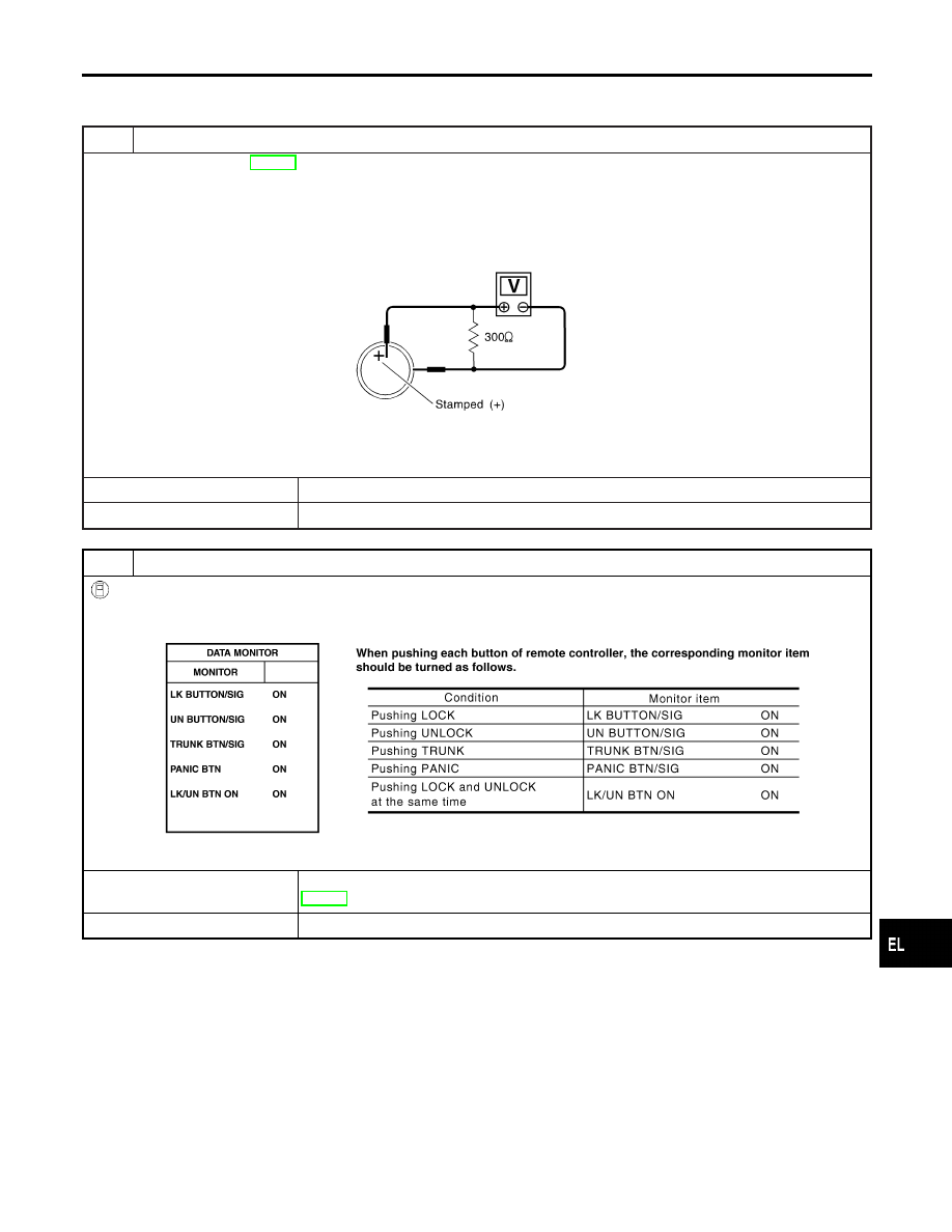
CHECK REMOTE CONTROLLER BATTERY

Remove battery (refer to EL-365) and measure voltage across battery positive and negative terminals, (+) and (−).

Voltage [V]:

2.5 - 3.0

NOTE:
Remote controller does not function if battery is not set correctly.

SEL237W

OK or NG

OK

©

GO TO 2.

NG

©

Replace battery.

2

CHECK REMOTE CONTROLLER FUNCTION

With CONSULT-II

Check remote controller function (“LK BUTTON/SIG”, “UN BUTTON/SIG”, “TRUNK BTN/SIG”, “PANIC BTN” and “LK/UN
BTN ON”) in “DATA MONITOR” mode with CONSULT-II.

SEL023Y

OK or NG

OK

©

Remote controller is OK. Further inspection is necessary. Refer to “SYMPTOM CHART”,
EL-347.

NG

©

Replace remote controller. Refer to ID Code Entry Procedure.

GI

MA

EM

LC

EC

FE

AT

AX

SU

BR

ST

RS

BT

HA

SC

IDX

MULTI-REMOTE CONTROL SYSTEM

Trouble Diagnoses (Cont’d)

EL-349

POWER SUPPLY AND GROUND CIRCUIT CHECK

=NHEL0195S03

1

CHECK MAIN POWER SUPPLY CIRCUIT FOR SMART ENTRANCE CONTROL UNIT

1. Disconnect smart entrance control unit harness connector.
2. Check voltage between smart entrance control unit harness connector M145 terminal 49 (R/B) or 51 (W/R) and ground.

SEL018Y

Refer to wiring diagram in EL-341.

OK or NG

OK

©

GO TO 2.

NG

©

Check the following.

I

40A fusible link (letter I, located in fuse and fusible link box)

I

10A fuse [No. 13, located in fuse block (J/B)]

I

E90 circuit breaker

I

Harness for open or short between smart entrance control unit and fuse

2

CHECK IGNITION SWITCH “ACC” CIRCUIT

1. Disconnect smart entrance control unit harness connector.
2. Check voltage between smart entrance control unit harness connector M144 terminal 26 (PU) and ground while ignition

switch is “ACC”.

SEL019Y

Refer to wiring diagram in EL-341.

OK or NG

OK

©

GO TO 3.

NG

©

Check the following.

I

10A fuse [No. 1, located in fuse block (J/B)]

I

Harness for open or short between smart entrance control unit and fuse

MULTI-REMOTE CONTROL SYSTEM

Trouble Diagnoses (Cont’d)

EL-350

3

CHECK GROUND CIRCUIT FOR SMART ENTRANCE CONTROL UNIT

Check continuity between smart entrance control unit harness connector M144 terminals 43 (B) or M145 terminal 64 (B)
and ground.

SEL020Y

Refer to wiring diagram in EL-341.

OK or NG

OK

©

Power supply and ground circuits are OK.

NG

©

Check ground harness.

GI

MA

EM

LC

EC

FE

AT

AX

SU

BR

ST

RS

BT

HA

SC

IDX

MULTI-REMOTE CONTROL SYSTEM

Trouble Diagnoses (Cont’d)

EL-351

DOOR SWITCH CHECK

=NHEL0195S04

1

CHECK DOOR SWITCH INPUT SIGNAL

With CONSULT-II

Check door switches (“DOOR SW-RR”, “DOOR SW-DR” and “DOOR SW-AS”) in “DATA MONITOR” mode with CON-
SULT-II.

SEL024Y

Without CONSULT-II

Check voltage between smart entrance control unit harness connector M143 terminals 1 (SB), 2 (R/L) or 3 (R/W) and
ground.

SEL021Y

Refer to wiring diagram in EL-342.

OK or NG

OK

©

Door switch is OK.

NG

©

GO TO 2.

2

CHECK DOOR SWITCH

1. Disconnect door switch harness connector.
2. Check continuity between door switch terminals.

SEL192W

OK or NG

OK

©

Check the following.

I

Door switch ground circuit or door switch ground condition

I

Harness for open or short between smart entrance control unit and door switch

NG

©

Replace door switch.

MULTI-REMOTE CONTROL SYSTEM

Trouble Diagnoses (Cont’d)

EL-352


Content   ..  418  419  420  421   ..