Infiniti I30 (A33). Manual - part 293
Wiring Diagram
NHEC0552
MEC758C
SEF629XB
GI
MA
EM
LC
FE
AT
AX
SU
BR
ST
RS
BT
HA
SC
EL
IDX
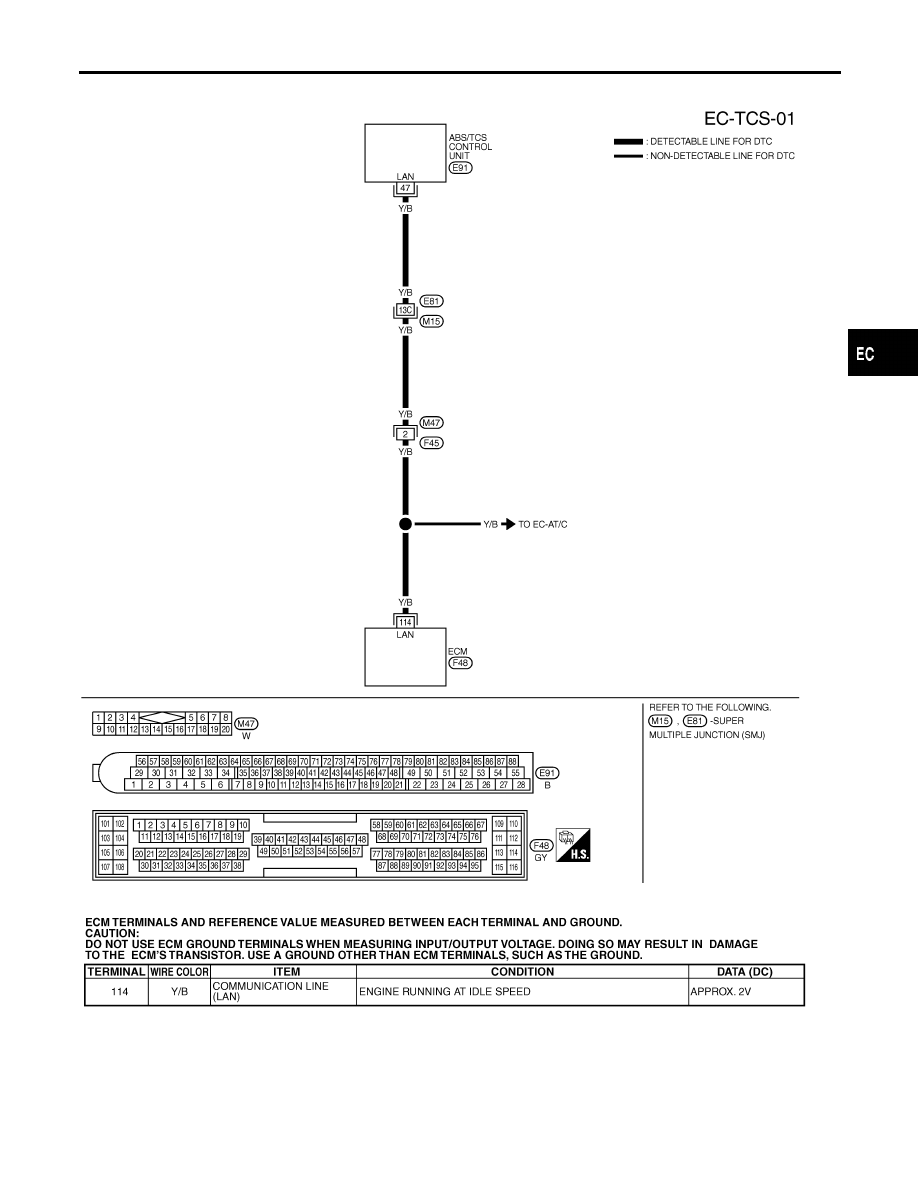
DTC P1212 ABS/TCS COMMUNICATION LINE
Wiring Diagram
EC-487
|
|
|
Wiring Diagram NHEC0552 MEC758C SEF629XB GI MA EM LC FE AT AX SU BR ST RS BT HA SC EL IDX DTC P1212 ABS/TCS COMMUNICATION LINE Wiring Diagram EC-487 |