Infiniti G37 Coupe. Manual - part 634
CYLINDER BLOCK
EM-111
< DISASSEMBLY AND ASSEMBLY >
C
D
E
F
G
H
I
J
K
L
M
A
EM
N
P
O
Disassembly and Assembly
INFOID:0000000001547566
DISASSEMBLY
1.
Remove the following parts:
• Oil pans (lower and upper): Refer to
.
• Front and rear timing chain case: Refer to
.
2.
Remove knock sensor.
CAUTION:
Carefully handle sensor avoiding shocks.
3.
Remove baffle plate from lower cylinder block.
4.
Remove piston and connecting rod assembly with the following procedure:
• Before removing piston and connecting rod assembly, check the connecting rod side clearance. Refer to
EM-148, "Connecting Rod Bearing"
CAUTION:
Be careful not to drop connecting rod bearing, and to scratch the surface.
a.
Position crankshaft pin corresponding to connecting rod to be removed onto the bottom dead center.
b.
Remove connecting rod bearing cap.
c.
Using a hammer handle or similar tool, push piston and connect-
ing rod assembly out to the cylinder head side.
CAUTION:
Be careful not to damage the cylinder wall and crankshaft
pin, resulting from an interference of the connecting rod big
end.
5.
Remove connecting rod bearings from connecting rod and connecting rod bearing cap.
CAUTION:
• Be careful not to drop connecting rod bearing, and to scratch the surface.
• Identify installation positions, and store them without mixing them up.
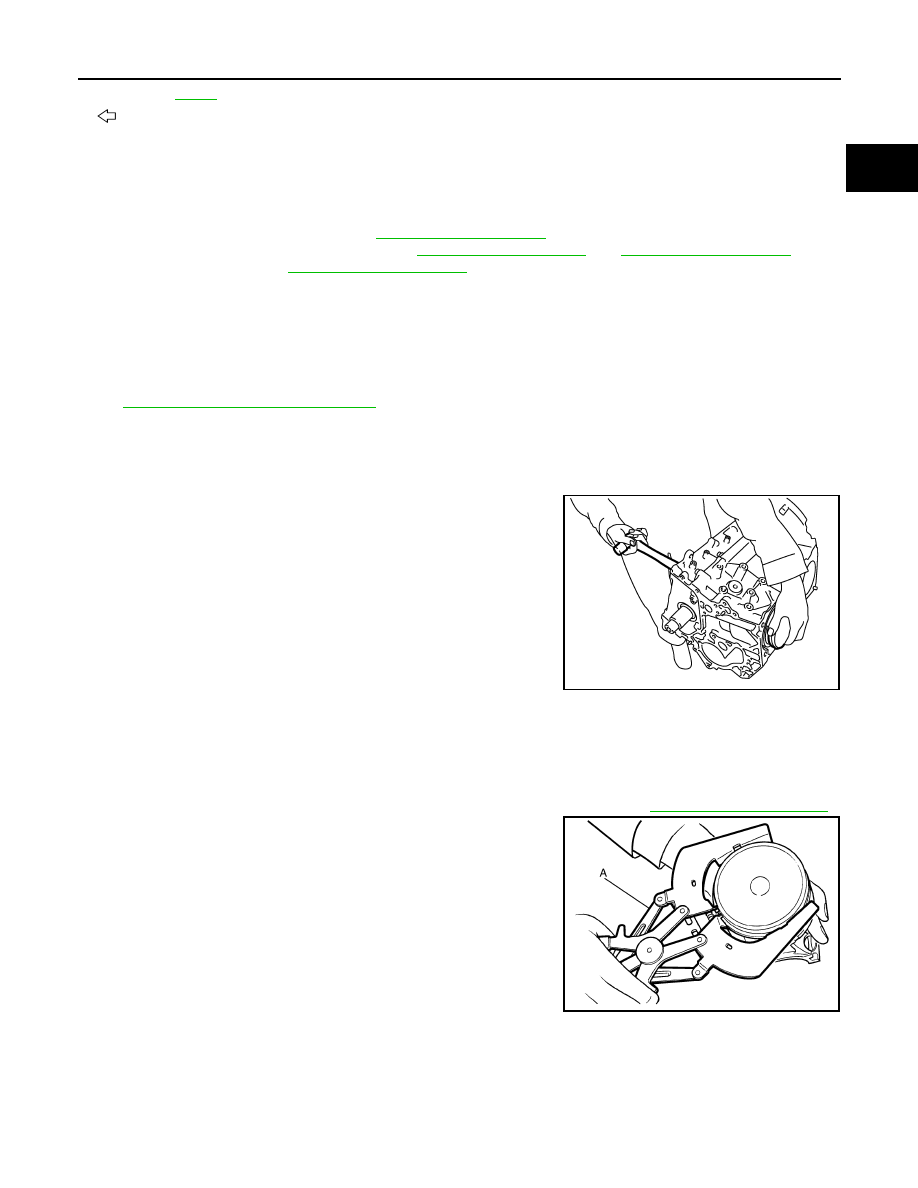
6.
Remove piston rings from piston.
• Before removing piston rings, check the piston ring side clearance. Refer to
.
• Use a piston ring expander (commercial service tool) (A).
CAUTION:
• When removing piston rings, be careful not to damage
piston.
• Be careful not to damage piston rings by expanding them
excessively.
7.
Remove piston from connecting rod as follows:
A.
Refer to
B.
Chamfered
C.
Front mark
: Crankshaft side
PBIC2940E
JPBIA0194ZZ