Infiniti G37 Coupe. Manual - part 632
CYLINDER HEAD
EM-103
< DISASSEMBLY AND ASSEMBLY >
C
D
E
F
G
H
I
J
K
L
M
A
EM
N
P
O
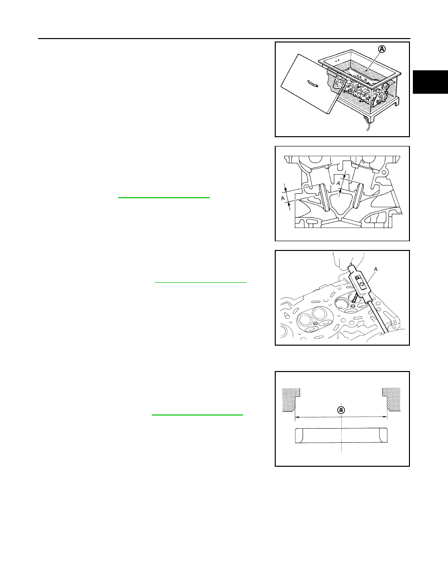
b.
Heat cylinder head to 110 to 130
°
C (230 to 266
°
F) by soaking in
heated oil (A).
c.
Using the valve guide drift (commercial service tool), press valve
guide (EXH) from camshaft side to the dimensions as shown in
the figure.
WARNING:
Cylinder head contains heat. When working, wear protec-
tive equipment to avoid getting burned.
d.
Using the valve guide reamer (commercial service tool) (A),
apply reamer finish to valve guide (EXH).
2.
If valve seat (EXH) is removed in step 10 (DISASSEMBLY), install it.
Replace with oversize [0.5 mm (0.020 in)] valve seat (EXH).
a.
Ream cylinder head recess diameter (a) for service valve seat
(EXH).
• Be sure to ream in circles concentric to valve guide center.
This will enable valve to fit correctly.
JPBIA0184ZZ
Projection (A)
: Refer to
JPBIA0186ZZ
Standard
: Refer to
.
JPBIA0185ZZ
Oversize (service) [0.5 mm (0.020 in)]:
: Refer to
.
JPBIA0188ZZ