Infiniti G37 Coupe. Manual - part 630
CAMSHAFT
EM-95
< DISASSEMBLY AND ASSEMBLY >
C
D
E
F
G
H
I
J
K
L
M
A
EM
N
P
O
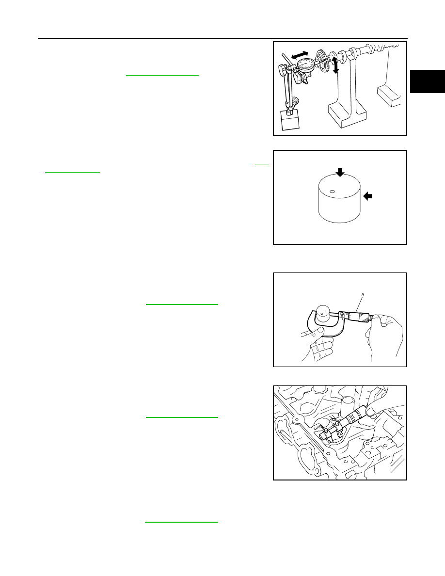
2.
Measure the camshaft sprocket (EXH) runout with a dial indica-
tor. (Total indicator reading)
3.
If it exceeds the limit, replace camshaft sprocket (EXH).
Valve Lifter (EXH)
• Check if surface of valve lifter has any wear or crack.
• If wear or crack is found, replace valve lifter (EXH). Refer to
Valve Lifter Clearance (EXH)
VALVE LIFTER OUTER DIAMETER
• Measure the outer diameter at 1/2 height of valve lifter with a
micrometer (A) since valve lifter is in barrel shape.
VALVE LIFTER HOLE DIAMETER
• Measure the inner diameter of valve lifter hole of cylinder head with
an inside micrometer.
VALVE LIFTER CLEARANCE
• (Valve lifter clearance) = (Valve lifter hole diameter) – (Valve lifter outer diameter)
• If the calculated value is out of the standard, referring to each standard of valve lifter outer diameter and
valve lifter hole diameter, replace either or both valve lifter and VVEL ladder assembly & cylinder head
assembly.
Limit
: Refer to
PBIC0930E
KBIA0182E
Standard
: Refer to
.
JPBIA0125ZZ
Standard
: Refer to
.
SEM867E
Standard
: Refer to
.