Content .. 1291 1292 1293 1294 ..
Infiniti G37 Coupe. Manual - part 1293
TRANSMISSION ASSEMBLY
TM-25
< REMOVAL AND INSTALLATION >
[6MT: FS6R31A]
C
E
F
G
H
I
J
K
L
M
A
B
TM
N
O
P
REMOVAL AND INSTALLATION
TRANSMISSION ASSEMBLY
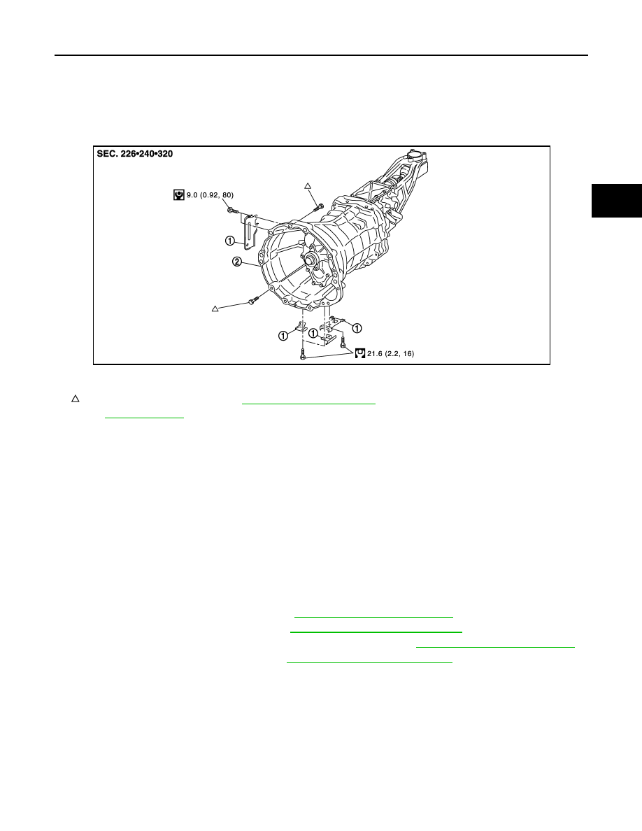
Exploded View
INFOID:0000000001732877
CAUTION:
If transmission assembly is removed from the vehicle, always replace CSC (Concentric Slave Cylinder) body and CSC tube.
Return CSC body insert to original position to remove transmission assembly. Dust on clutch disc sliding parts may damage
seal of CSC body and may cause clutch fluid leakage.
Removal and Installation
INFOID:0000000001732878
CAUTION:
If transmission assembly is removed from the vehicle, always replace CSC (Concentric Slave Cylin-
der) body and CSC tube. Return CSC body insert to original position to remove transmission assem-
bly. Dust on clutch disc sliding parts may damage seal of CSC body and may cause clutch fluid
leakage.
REMOVAL
1.
Disconnect the battery cable from the negative terminal.
2.
Remove exhaust mounting bracket. Refer to
EX-6, "Removal and Installation"
3.
Remove suspension member stay. Refer to
FSU-24, "Removal and Installation"
4.
Remove exhaust front tube, center muffler, and main muffler. Refer to
EX-6, "Removal and Installation"
5.
Remove propeller shaft assembly. Refer to
DLN-7, "Removal and Installation"
.
NOTE:
Insert a suitable plug into rear oil seal of transmission assembly after removing propeller shaft assembly.
6.
Remove control lever assembly with the following procedure.
1.
Harness bracket
2.
Transmission assembly
: For the bolt mounting positions, refer to
TM-25, "Removal and Installation"
.
Refer to
for symbols not described on the above.
JPDIC0158GB