Infiniti G35 (V35) Sedan. Manual - part 438
DLN-186
< DISASSEMBLY AND ASSEMBLY >
[REAR FINAL DRIVE: R200]
DIFFERENTIAL ASSEMBLY
CAUTION:
Never change the total amount of washers as it will change the bearing preload.
2WD : Inspection After Disassembly
INFOID:0000000000957399
Clean up the disassembled parts. Then, inspect if the parts are worn or damaged. If so, follow the measures
below.
AWD
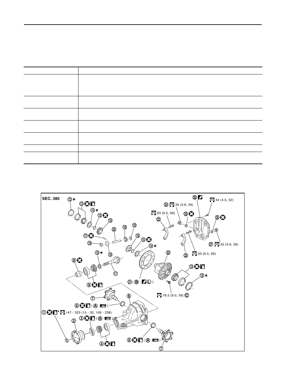
AWD : Exploded View
INFOID:0000000000957400
Content
Conditions and Measures
Hypoid gear
• If the gear teeth do not mesh or line-up correctly, determine the cause and adjust or replace as nec-
essary.
• If the gears are worn, cracked, damaged, pitted or chipped (by friction) noticeably, replace with new
drive gear and drive pinion as a set.
Bearing
• If any chipped (by friction), pitted, worn, rusted or scratched mark, or unusual noise from the bearing
is observed, replace as a bearing assembly (as a new set).
Side gear and Pinion mate
gear
• If any cracks or damage on the surface of the tooth is found, replace.
• If any worn or chipped mark on the contact sides of the thrust washer is found, replace.
Side gear thrust washer and
pinion mate thrust washer
• If it is chipped (by friction), damaged, or unusually worn, replace.
Oil seal
• Whenever disassembled, replace.
• If wear, deterioration of adherence (sealing force lips), or damage is detected on the lips, replace them.
Differential case
• If any wear or crack on the contact sides of the differential case is found, replace.
Companion flange
• If any chipped mark (about 0.1 mm, 0.004 in) or other damage on the contact sides of the lips of the
companion flange is found, replace.
JSDIA0027GB