Infiniti G35 (V35) Sedan. Manual - part 384
RADIATOR CORE SUPPORT
DLK-197
< ON-VEHICLE REPAIR >
[INTELLIGENT KEY SYSTEM]
C
D
E
F
G
H
I
J
L
M
A
B
DLK
N
O
P
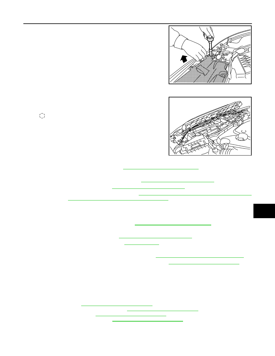
In the case that only radiator core support ornament is
removed (front bumper is not removed), remove them accord-
ing to the procedures shown below.
- To remove the mounting bolts on both sides of radiator core
support ornament, first remove the mounting bolts of front
bumper (shown by arrows in the figure) and pull up the
bumper edge slightly to get working clearance.
CAUTION:
Do not apply excessive force while pulling front bumper
to prevent front bumper and front fender from being dam-
aged.
• Hold both sides of radiator core support ornament, pull it upwards and slide it to the rear of the vehicle.
• Disconnect the harness clip and hood lock control cable clip
on radiator core support.
5.
Remove the head lamp assembly. Refer to
EXL-185, "Removal and Installation"
.
6.
Remove the hood lock bracket assembly.
7.
Remove the washer inlet and washer tank. Refer to
WW-79, "Removal and Installation"
8.
Remove the ambient sensor. Refer to
VTL-25, "Removal and Installation"
.
9.
Remove the power steering fluid cooler. Refer to
ST-20, "WITHOUT 4WAS : Removal and Installation"
(without 4WAS),
ST-22, "WITH 4WAS : Removal and Installation"
(with 4WAS).
10. Remove the air guide mounting clips and then remove air guaide.
11. Disconnect the harness connector from liquid tank, and disconnect harness clamp from radiator core sup-
port.
12. Remove the ICC sensor integrated unit. Refer to
CCS-110, "Removal and Installation"
.
13. Remove the hood lock stay.
14. Remove the engine undercover. Refer to
EXT-26, "Removal and Installation"
15. Drain engine coolant from radiator. Refer to
.
16. Remove the radiator upper hose and lower hose on radiator side.
17. Remove the A/T fluid cooler tube on radiator side. Refer to
TM-271, "2WD : Removal and Installation"
18. Disconnect condenser pipe assembly at one touch joint. Refer to
HA-54, "Removal and Installation"
19. Remove the radiator core support assembly mounting bolts, and draw out radiator core support assembly
forward of the vehicle.
20. Disconnect the cooling fan and crush zone sensor harness connector and clamp.
21. Remove the radiator core support assembly.
22. Remove the following parts after removing the radiator core support assembly.
• Head lamp bracket.
• Cooling fan. Refer to
CO-17, "Removal and Installation"
• Radiator and condenser assembly. Refer to
CO-14, "Removal and Installation"
.
• Crush zone sensor Refer to
SR-14, "Removal and Installation"
.
• Crush zone sensor bracket Refer to
SR-14, "Removal and Installation"
INSTALLATION
Install in the reverse order of removal.
CAUTION:
JMKIA0140ZZ
: Clip
JMKIA0141ZZ