Infiniti G35 (V35) Sedan. Manual - part 313
 

  Index      Infiniti     Infiniti G35 (V35) Sedan - service repair manual 2007 year


Search            


Content   ..  311  312  313  314   ..


Infiniti G35 (V35) Sedan. Manual - part 313


CL-22

< SERVICE DATA AND SPECIFICATIONS (SDS) 

SERVICE DATA AND SPECIFICATIONS (SDS)

SERVICE DATA AND SPECIFICATIONS (SDS)

SERVICE DATA AND SPECIFICATIONS (SDS)

Clutch Control System

INFOID:0000000000956940

Clutch Pedal

INFOID:0000000000956941

Unit: mm (in)

Clutch Master Cylinder

INFOID:0000000000956942

Unit: mm (in)

Clutch Disc

INFOID:0000000000956943

Unit: mm (in)

Clutch Cover

INFOID:0000000000956944

Type of clutch control

Hydraulic

Clearance 

″

C

″

 between pedal stopper rubber and clutch interlock 

switch threaded while clutch pedal is fully depressed.

0.1 - 1.0 (0.004 - 0.039)

Inner diameter

17.46 (11/16)

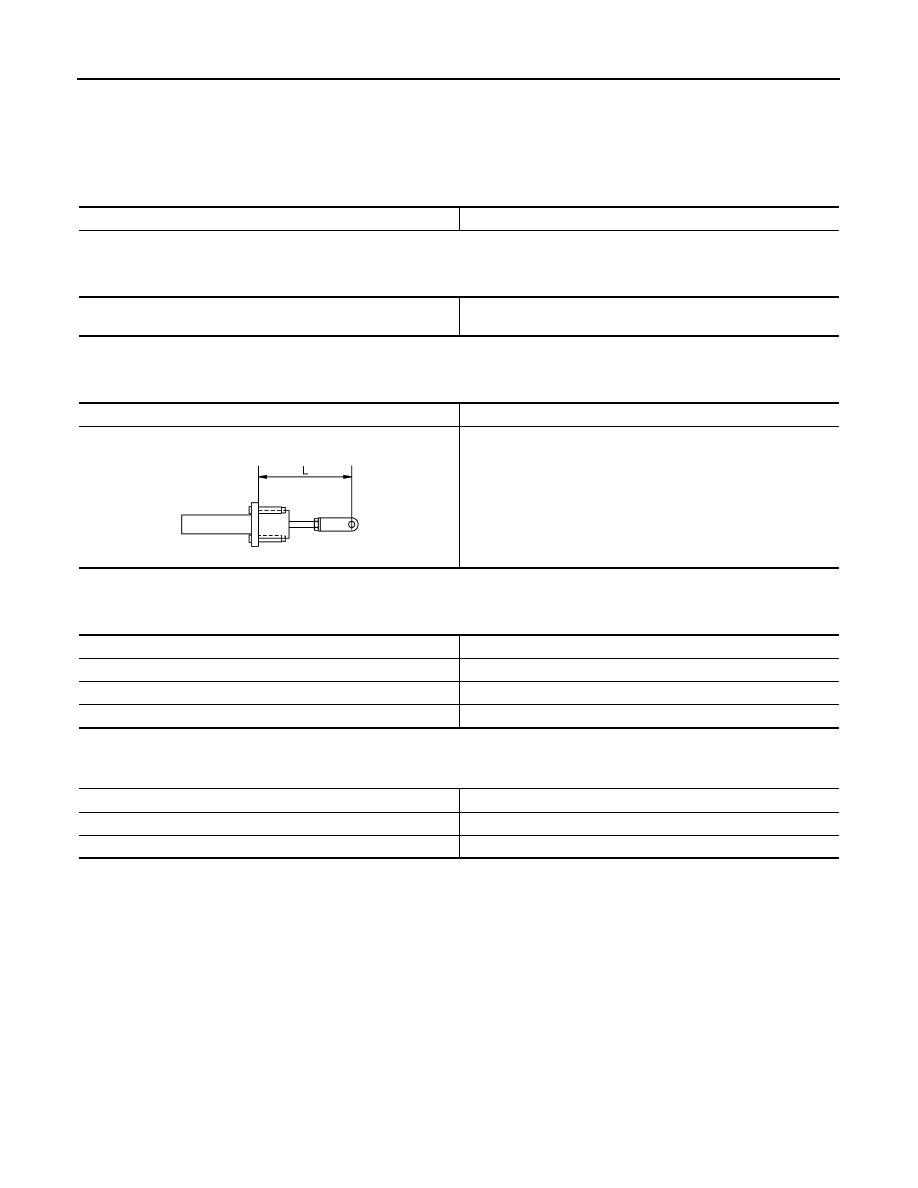
Standard length “L” between clevis and push rod

133.0 - 133.9 (5.24 - 5.27)

JPDIB0029ZZ

Facing size (Outer dia. 

×

 Inner dia. 

×

 Thickness)

240 

×

 160 

×

 3.5 (9.45 

×

 6.30 

×

 0.138)

Runout limit/diameter of the area to be measured

1.0 (0.039) /230 (9.06) dia.

Maximum allowable spline backlash (at outer edge of disc)

1.0 (0.039)

Facing wear limit (depth to the rivet head)

0.3 (0.012)

Set-load

10,300 N (1,050.6 kg, 2,315.4 lb)

Tolerance for diaphragm spring lever unevenness

0.8 mm (0.031 in) or less

Diaphragm spring lever height

44.7 - 46.7 mm (1.760 - 1.839 in)

CO-1

ENGINE

C

D

E

F

G

H

I

J

K

L

M

SECTION 

CO

A

CO

N

O

P

CONTENTS

ENGINE COOLING SYSTEM

FUNCTION DIAGNOSIS ...............................

2

DESCRIPTION ....................................................

2

Engine Cooling System ...........................................

2

Engine Cooling System Schematic .........................

2

SYMPTOM DIAGNOSIS  ...............................

3

OVERHEATING CAUSE ANALYSIS  ..................

3

Troubleshooting Chart ..............................................

3

PRECAUTION ...............................................

5

PRECAUTIONS ...................................................

5

Precaution for Supplemental Restraint System 
(SRS) "AIR BAG" and "SEAT BELT PRE-TEN-
SIONER" .................................................................
..

5

Liquid Gasket ...........................................................

5

PREPARATION ............................................

7

PREPARATION ...................................................

7

Special Service Tools ..............................................

7

Commercial Service Tools .......................................

7

ON-VEHICLE MAINTENANCE .....................

8

ENGINE COOLANT  ............................................

8

Inspection ..................................................................

8

Draining .....................................................................

8

Refilling .....................................................................

9

Flushing ...................................................................

10

RADIATOR .........................................................

12

RADIATOR CAP ........................................................

12

RADIATOR CAP : Inspection ..................................

12

RADIATOR ................................................................

12

RADIATOR : Inspection  ..........................................

12

ON-VEHICLE REPAIR .................................

14

RADIATOR ........................................................

14

Exploded View .........................................................

14

Removal and Installation  .........................................

14

Inspection ................................................................

16

COOLING FAN ..................................................

17

Exploded View .........................................................

17

Removal and Installation  .........................................

17

Inspection ................................................................

17

Disassembly and Assembly .....................................

17

Inspection ................................................................

18

WATER PUMP  ..................................................

19

Exploded View .........................................................

19

Removal and Installation  .........................................

19

Inspection ................................................................

21

WATER INLET AND THERMOSTAT ASSEM-
BLY ....................................................................

22

Exploded View .........................................................

22

Removal and Installation  .........................................

22

Inspection ................................................................

23

WATER OUTLET AND WATER PIPING  ..........

24

Exploded View .........................................................

24

Removal and Installation  .........................................

24

Inspection ................................................................

25

SERVICE DATA AND SPECIFICATIONS 
(SDS) ............................................................

26

SERVICE DATA AND SPECIFICATIONS 
(SDS) .................................................................

26

Periodical Maintenance Specification ....................

26

Radiator ...................................................................

26

Thermostat ..............................................................

26

CO-2

< FUNCTION DIAGNOSIS >

DESCRIPTION

FUNCTION DIAGNOSIS

DESCRIPTION

Engine Cooling System

INFOID:0000000000956331

Engine Cooling System Schematic

INFOID:0000000000956332

JPBIA0248GB

JPBIA0249GB

OVERHEATING CAUSE ANALYSIS

CO-3

< SYMPTOM DIAGNOSIS >

C

D

E

F

G

H

I

J

K

L

M

A

CO

N

P

O

SYMPTOM DIAGNOSIS

OVERHEATING CAUSE ANALYSIS

Troubleshooting Chart

INFOID:0000000000956333

Symptom

Check items

Cooling sys-
tem parts 
malfunction

Poor heat transfer

Water pump malfunction

Worn or loose drive belt

—

Thermostat stuck closed

—

Damaged fins

Dust contamination or pa-
per clogging

Physical damage

Clogged radiator cooling 
tube

Excess foreign material 
(rust, dirt, sand, etc.)

Reduced air flow

Cooling fan does not oper-
ate

Fan assembly

—

High resistance to fan rota-
tion

Damaged fan blades

Damaged radiator shroud

—

—

—

Improper engine coolant 
mixture ratio

—

—

—

Poor engine coolant quality

—

Engine coolant density

—

Insufficient engine coolant

Engine coolant leaks

Cooling hose

Loose clamp

Cracked hose

Water pump

Poor sealing

Radiator cap

Loose

Poor sealing

Radiator

O-ring for damage, deterio-
ration or improper fitting

Cracked radiator tank

Cracked radiator core

Reservoir tank

Cracked reservoir tank

Overflowing reservoir tank

Exhaust gas leaks into cool-
ing system

Cylinder head deterioration

Cylinder head gasket deteri-
oration


Content   ..  311  312  313  314   ..