Infiniti G35 (V35) Sedan. Manual - part 310


  Index      Infiniti     Infiniti G35 (V35) Sedan - service repair manual 2007 year


Search            


Content   ..  308  309  310  311   ..


Infiniti G35 (V35) Sedan. Manual - part 310


CL-10

< ON-VEHICLE REPAIR >

CLUTCH MASTER CYLINDER

6.

Remove reservoir tank assembly.

7.

Remove clutch tube using a flare nut wrench.

8.

Remove packing (1) and master cylinder assembly (2).

CAUTION:

Be careful not to damage packing, brake booster, and dash
lower.

INSTALLATION

CAUTION:

Keep painted surface on the body or other parts free of clutch fluid. If it spills, wipe up immediately
and wash the affected area with water.
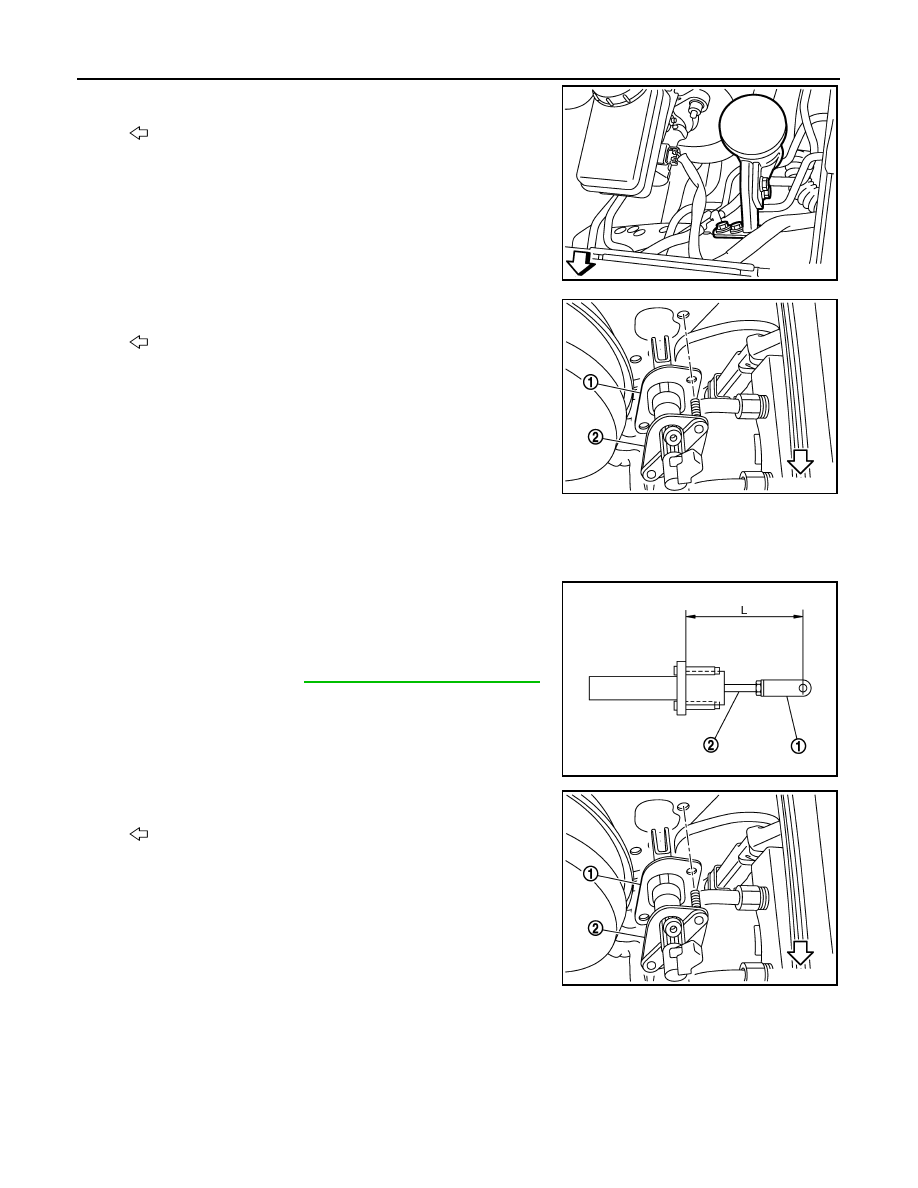
1.

Check position of clevis (1) and push rod (2). If measurement is
outside the standard length, adjust position of clevis and push
rod. After adjusting length, tighten lock nut to the specified
torque.

2.

Install packing (1) and master cylinder assembly (2).

CAUTION:

• Be careful not to damage packing, brake booster, and

dash lower.

: Vehicle front

JPDIB0008ZZ

: Vehicle front

JPDIB0009ZZ

Length “L”

: Refer to 

CL-22, "Clutch Master Cylinder"

.

JPDIB0014ZZ

: Vehicle front

JPDIB0009ZZ

CLUTCH MASTER CYLINDER

CL-11

< ON-VEHICLE REPAIR >

C

E

F

G

H

I

J

K

L

M

A

B

CL

N

O

P

• Be careful with the orientation of packing. The figure is

the view from the vehicle forward.

3.

Connect clutch tube to master cylinder assembly and tempo-
rarily tighten flare nut.

4.

Install master cylinder assembly and tighten mounting nuts to
the specified torque.

5.

Tighten clutch tube flare nut to the specified torque using a flare
nut torque wrench. Refer to 

CL-13, "Exploded View"

.

6.

Set clevis to clutch pedal assembly.

7.

Apply recommended grease to clevis pin and then insert clevis
pin to clevis.

8.

Attach snap pin to clevis pin.

9.

Install hose (1) and clips to reservoir tank assembly (2) and
master cylinder assembly (3).

CAUTION:

Set hose with painted mark facing upward.

10. After completing this procedure, inspect and adjust for clutch

pedal and then bleed the air from the clutch hydraulic system.
Refer to 

CL-5, "Inspection and Adjustment"

 and 

CL-6, "Air

Bleeding Procedure"

.

11. Install brake master cylinder cover. Refer to 

EXT-18, "Removal

and Installation"

.

12. Install instrument driver lower panel. Refer to 

IP-12, "Removal and Installation"

.

13. Install dash side finisher and front kicking plate inner. Refer to 

INT-13, "Removal and Installation"

.

Disassembly and Assembly

INFOID:0000000000956930

DISASSEMBLY

1.

Loosen push rod lock nut and then remove clevis and lock nut, if necessary.
NOTE:
Clutch pedal height is controlled with position of clevis and push rod.

2.

Remove boot.

3.

Remove stopper ring.

4.

Remove push rod while holding it securely to prevent piston
assembly popping out.

5.

Remove piston assembly and return spring.

ASSEMBLY

1.

Apply rubber lubricant to the internal surface of cylinder body, the sliding surface and piston cup of piston
assembly.

2.

Insert return spring and piston assembly to cylinder body.

3.

Apply silicon grease to push rod.

4.

Install stopper ring while holding down push rod by hand to prevent piston assembly from popping out.

CAUTION:

Do not reuse stopper ring.

5.

Install boot to cylinder body.

: Painted mark

JPDIB0010ZZ

JPDIB0011ZZ

JPDIB0013ZZ

CL-12

< ON-VEHICLE REPAIR >

CLUTCH MASTER CYLINDER

6.

Install lock nut and clevis to push rod.

7.

Check and adjust the positions of clevis (1) and push rod (2).
After adjusting length, tighten lock nut to the specified torque.

Inspection

INFOID:0000000000956931

INSPECTION AFTER DISASSEMBLY

Check for any of the conditions shown below. If any malfunction is found, replace the part concerned.
• Damaged cylinder internal wall, foreign matter, wear, corrosion.
• Damaged or deformed reservoir tank.
• Settling of return spring.
• Cracked or deformed boot.
• Cracked or deformed packing.

Length “L”

: Refer to 

CL-22, "Clutch Master Cylinder"

.

JPDIB0014ZZ

CLUTCH PIPING

CL-13

< ON-VEHICLE REPAIR >

C

E

F

G

H

I

J

K

L

M

A

B

CL

N

O

P

CLUTCH PIPING

Exploded View

INFOID:0000000000956932

Hydraulic Layout

INFOID:0000000000956933

Removal and Installation

INFOID:0000000000956934

1.

CSC (Concentric Slave Cylinder) as-
sembly 

2.

Bracket

3.

Clutch hose

4.

Lock plate

5.

Clutch tube

6.

Connector

7.

Master cylinder assembly

Refer to 

GI-4, "Components"

 for the symbols in the figure.

JPDIB0015GB

1.

CSC (Concentric Slave Cylinder) as-
sembly

2.

Clutch tube

3.

Clutch hose

4.

Connector

5.

Master cylinder assembly

JPDIB0016ZZ


Content   ..  308  309  310  311   ..