Infiniti G35 (V35) Sedan. Manual - part 308


  Index      Infiniti     Infiniti G35 (V35) Sedan - service repair manual 2007 year


Search            


Content   ..  306  307  308  309   ..


Infiniti G35 (V35) Sedan. Manual - part 308


CL-2

< SYMPTOM DIAGNOSIS >

NOISE, VIBRATION AND HARSHNESS (NVH) TROUBLESHOOTING

SYMPTOM DIAGNOSIS

NOISE, VIBRATION AND HARSHNESS (NVH) TROUBLESHOOTING

NVH Troubleshooting Chart

INFOID:0000000000956919

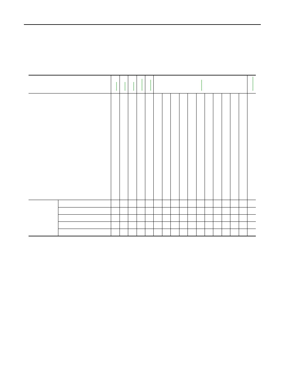
Use the chart below to help you find the cause of the symptom. The numbers indicate the order of the inspec-
tion. If necessary, repair or replace these parts.

Reference

CL

-5

CL

-6

CL

-9

EM-77

CL

-1

5

CL

-1

9

EM-124

SUSPECTED PARTS (Possible cause)

CLUTCH P

E

DAL (I

ns

pe

cti

o

n

 a

nd 

ad

jus

tm

e

n

t)

CLUTCH LINE (A

ir in line)

MAS

T

ER CYLINDER PIS

T

ON CUP (Damaged)

ENGINE MOU

N

TING (Loose)

CSC (Con

ce

nt

ric

 Sla

v

e

 Cy

lin

de

r) (W

orn

, di

rty

 or 

da

ma

ge

d)

CLUTCH DISC (Out 

of 

true)

CLUTCH DISC (Runou

t i

s

 ex

ce

ssi

v

e

)

CLUTCH DISC (Lining 

broken)

CLUTCH DISC (Dirty or burned)

CLUTCH DISC (Oily)

CLUTCH DISC (W

orn 

out)

CLUTCH DISC (Hardened)

CLUTCH DISC (Lack 

of

 sp

lin

e

 gre

a

s

e)

DI

APHRAGM SPRI

N

G (Dam

ag

ed

)

DIAPHRAGM

 SPRING (Ou

t of

 ti

p a

lig

nm

en

t)

PRESSURE P

L

A

T

E (Di

s

torti

on)

FL

YWHEE

L

 (Distortion)

Symptom

Clutch grabs/chatters

1

2

2

2

2

2

Clutch pedal spongy

1

2

2

Clutch noisy

1

Clutch slips

1

2

2

3

4

5

Clutch  does  not  disengage

1

2

3

4

4

4

4

4

4

4

5

5

6

PRECAUTIONS

CL-3

< PRECAUTION >

C

E

F

G

H

I

J

K

L

M

A

B

CL

N

O

P

PRECAUTION

PRECAUTIONS

Service Notice or Precautions for Clutch

INFOID:0000000000956920

CAUTION:

• Recommended clutch fluid is brake fluid “DOT 3”. Refer to 

MA-10, "Fluids and Lubricants"

.

• Never reuse drained clutch fluid.
• Be careful not to splash clutch fluid on painted areas.
• When removing clutch tube, use a flare nut wrench.
• When installing clutch tube, use a flare nut torque wrench.
• Use new clutch fluid to clean or wash all parts of master cylin-

der.

• Never use mineral oils such as gasoline or kerosene. It will

ruin the rubber parts of the hydraulic system.

• If transmission assembly is removed from the vehicle, always

replace CSC (Concentric Slave Cylinder) body and CSC tube.
Return CSC body insert to original position to remove trans-
mission assembly. Dust on clutch disc sliding parts may dam-
age seal of CSC body and may cause clutch fluid leakage.

• Do not disassemble CSC body.

WARNING:

After cleaning clutch disc, wipe it with a dust collector. Do not use compressed air.

SBR686C

CL-4

< PREPARATION >

PREPARATION

PREPARATION

PREPARATION

Special Service Tools

INFOID:0000000000956921

The actual shapes of Kent-Moore tools may differ from those of special service tools illustrated here.

Commercial Service Tools

INFOID:0000000000956922

Tool number
(Kent-Moore No.)
Tool name

Description

ST20050240
(

)

Diaphragm adjusting wrench

Adjusting unevenness of diaphragm spring of 
clutch cover

ST20670000
(

)

Clutch aligning bar
a: 15 mm (0.59 in) dia.
b: 23 mm (0.91 in) dia.

Installing clutch disc

ZZA0508D

ZZA1178D

Tool name

Description

1. Flare nut crowfoot
a: 10 mm (0.39 in)
2. Torque wrench

Installing clutch tube

Power tool

Loosening bolts and nuts

S-NT360

PBIC0190E

CLUTCH PEDAL

CL-5

< ON-VEHICLE MAINTENANCE >

C

E

F

G

H

I

J

K

L

M

A

B

CL

N

O

P

ON-VEHICLE MAINTENANCE

CLUTCH PEDAL

Inspection and Adjustment

INFOID:0000000000956923

INSPECTION

1.

Make sure that clevis pin (1) floats freely in the bore of clutch
pedal. It should not be bound by clevis or clutch pedal.

a.

If clevis pin is not free, make sure that ASCD clutch switch (2) is
not applying pressure to clutch pedal causing clevis pin to bind.
To adjust, loosen lock nut (3) and turn ASCD clutch switch.

b.

Tighten lock nut. Refer to 

CL-7, "Exploded View"

.

c.

Make sure that clevis pin floats in the bore of clutch pedal. It
should not be bound by clutch pedal.

d.

If clevis pin is still not free, remove clevis pin and check for
deformation or damage. Replace clevis pin if necessary. Leave
clevis pin removed for step 2.

2.

Check clutch pedal stroke for free range of movement.

a.

With clevis pin removed, manually move clutch pedal up and down to determine if it moves freely.

b.

If any sticking is found, replace related parts (bushing, clutch pedal assembly, etc.). Reassemble clutch
pedal and again make sure that clevis pin floats freely in the bore of clutch pedal.

3.

Check clutch hydraulic and system components (clutch master cylinder, CSC, etc.) for sticking or binding.

a.

If any sticking or binding is found, repair or replace related parts as necessary.

b.

If hydraulic system repair was necessary, bleed the clutch hydraulic system. Refer to 

CL-6, "Air Bleeding

Procedure"

.

ADJUSTMENT

1.

Adjust clutch interlock switch (1) position so that clearance
between stopper rubber (2) and thread end (A) of clutch inter-
lock switch with clutch pedal depressed is clearance “C”.

2.

After adjusting clearance “C”, tighten lock nut (3) to the specified
torque. Refer to 

CL-7, "Exploded View"

.

JPDIB0001ZZ

Clearance “C”

: Refer to 

CL-22, "Clutch Pedal"

.

JPDIB0002ZZ


Content   ..  306  307  308  309   ..